Null moving digital measuring device and method of aiming device based on target plate with composite image

A technology of measuring devices and graphics, applied in the direction of measuring devices, aiming devices, using optical devices, etc.

Inactive Publication Date: 2012-10-24
BEIJING INSTITUTE OF TECHNOLOGYGY
View PDF5 Cites 0 Cited by
  • Summary
  • Abstract
  • Description
  • Claims
  • Application Information

AI Technical Summary

Problems solved by technology

These measurement methods solve the high-precision measurement method of zero-position movement of low-light sights, but their devices cannot complete the zero-position movement test of infrared band sights

Method used


Image

  • Null moving digital measuring device and method of aiming device based on target plate with composite image
  • Null moving digital measuring device and method of aiming device based on target plate with composite image
  • Null moving digital measuring device and method of aiming device based on target plate with composite image

Examples


Embodiment 1

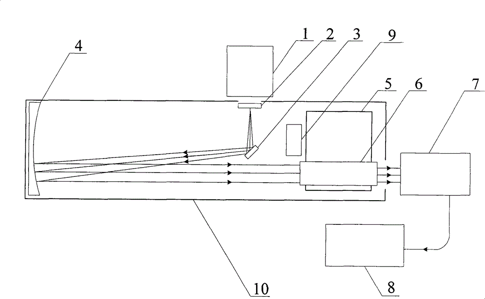
[0035] Such as figure 1 As shown, the zero-position digital measurement device of the sight based on the composite graphic target of the present invention comprises: a light source 1, a composite graphic target 2, a reflector 3, a main reflector 4, a fixture 5, an image analyzer 7, a computer 8. Temperature control module 9, casing 10; the composite graphic target plate 2 is illuminated by the light source 1, and then passes through the reflector 3 and the main reflector 4 in turn to form an image on the tested sight 6; the tested sight 6 Install the card on the fixture 5.

[0036] It includes a light source 1, a composite graphic target plate 2, a reflector 3, and a main reflector 4 for respectively generating infrared, visible and low-light images, wherein the light source 1 is an infrared blackbody.

[0037] It also includes a sight under test 6, an image analyzer 7, and a computer 8. When used to measure the sight under test 6 with an eyepiece, the computer 8 can collect...

Embodiment 2

[0044] Such as Figure 5 As shown, the zero-position digital measurement device of the sight based on the composite graphic target of the present invention includes: a light source 1, a composite graphic target 2, a reflector 3, a main reflector 4, a fixture 5, a computer 8, and a temperature control module 9. Case 10.

[0045] The difference from the first embodiment is that the tested sight 6 can directly output video images, so the video of the sight can be directly collected by a computer for processing. In the second embodiment, since the error factors such as the analyzer are removed, the test accuracy is higher.


PUM


Abstract

The invention relates to a null moving digital measuring device of an aiming device based on a target plate with a composite image, belonging to the technical field of optical precision measurement and comprising a light source, the target plate with a composite image, a reflecting mirror, a main reflecting mirror, a clamp apparatus, an image analyzer, a computer, a temperature control module anda casing. The device uses the light source to illume the target plate with a composite image so as to respectively generate multi-waveband composite aiming targets which are imaged on a measured aiming device after passing through the reflecting mirror and the main reflecting mirror, target images outputted by the aiming device are directly collected or images on a reticule are collected at an exit pupil position of the ocular of the aiming device by the image analyzer, then the digital image process is carried out on the images by measuring software after the images are input to the computer,and finally a measured result is calculated. The invention can be used for the high-precision detection of null moving of the ultrared visible low-light level aiming device and has the advantages ofhigh precision and objectivity as well as good real-time performance.

Description

technical field [0001] The invention is a digital measuring device for zero-position movement of sights based on a composite graphic target board, which can be used for high-precision detection of zero-position movement parameters of infrared and visible light sights in an indoor environment, and belongs to the technical field of optical precision measurement. technical background [0002] With the development of modern military science and technology, infrared, visible, and low-light sights have become common equipment in weapon systems. Sights are the eyes of light weapon systems. The use of sights has brought the weapon system to a higher level and greatly improved the weapon system. The comprehensive effectiveness of all-weather use makes the weapon system have the advantages of long observation distance, fast aiming speed and high shooting accuracy. The zero-position movement of the sight refers to the repeated loading error between the sight and the firearm and the mo...

Claims


Application Information

Patent Timeline
Patent Type & Authority Patents(China)
IPC IPC(8): G01B11/00F41G1/54
Inventor 林家明孙若端何川任建荣张旭升沙定国赵维谦周桃庚陈凌峰
Owner BEIJING INSTITUTE OF TECHNOLOGYGY
Why Eureka
Try Eureka