Three-dimensional looking forward sound imaging sonar system for underwater vehicle and using method thereof

A small water and carrier technology, applied in the radio wave measurement system, using re-radiation, re-radiation of sound waves, etc., can solve problems such as discomfort, large size of three-dimensional forward-looking sonar, and unsuitable installation

Inactive Publication Date: 2009-11-18
INST OF ACOUSTICS CHINESE ACAD OF SCI
View PDF0 Cites 17 Cited by
  • Summary
  • Abstract
  • Description
  • Claims
  • Application Information

AI Technical Summary

Problems solved by technology

However, due to the use of planar arrays, the number of array elements is large and the system is complex, it is limited when installed on underwater vehicles, especially not suitable for small underwater vehicles, and its resolution in the vertical direction is limited by Fourier transform, so the resolution is low
[0005] At present, the development of three-dimensional forward-looking sonar has been serialized, and the technological level is very high, but the resolution of the developed sonar is limited by the conventional beamforming, that is, the beam angle width Δθ~λ / L, λ is the wavelength of the center frequency, and L is Sonar array length
Generally, the size of the three-dimensional forward-looking sonar is large, and it is not suitable for installation on small underwater vehicles such as small autonomous underwater vehicles (AUV). Currently, the first multi-beam forward-looking imaging is mainly installed on small AUVs. Sonar, cannot directly give three-dimensional information of the target

Method used


Image

  • Three-dimensional looking forward sound imaging sonar system for underwater vehicle and using method thereof
  • Three-dimensional looking forward sound imaging sonar system for underwater vehicle and using method thereof
  • Three-dimensional looking forward sound imaging sonar system for underwater vehicle and using method thereof

Examples


Embodiment Construction

[0050] A three-dimensional forward-looking audio-visual sonar system and method based on DOA estimation provided by the present invention will be described in detail below in conjunction with the accompanying drawings and specific embodiments.

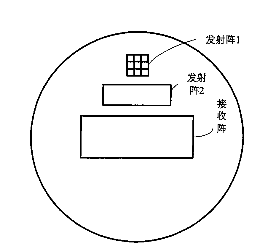
[0051] figure 1 It is a structural diagram of a sonar system according to an embodiment of the present invention, such as figure 1 As shown, the sonar system includes 2 transmitting sonar arrays and 1 receiving sonar array, which are located in front of the underwater chassis.

[0052]The sonar system adopts the mode of dual emission array switching of emission array 1 and emission array 2. The short-distance detection adopts the emission array 1 to ensure the coverage width; the long-distance detection adopts the emission array 2 to improve the working distance of the coverage area.

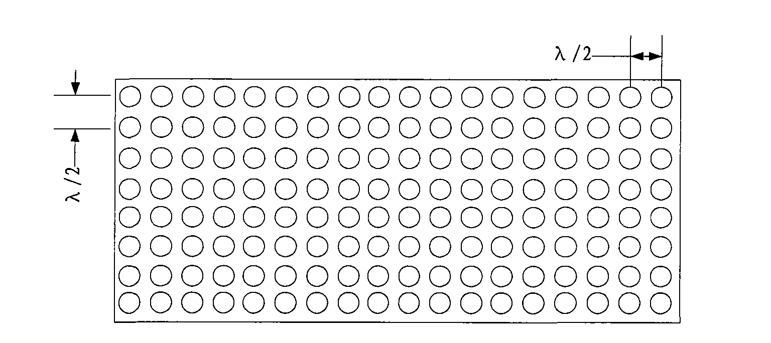
[0053] The emission array 1 is composed of 3*3=9 primitives, and the distance between the primitives is half a wavelength. The central primitive is la...


PUM


Abstract

The invention discloses a three-dimensional looking forward sound imaging sonar system for an underwater vehicle, which comprises a sonar transmitting array 1, a sonar transmitting array 2 and a sonar receiving array, wherein the sonar transmitting array 1 is used for short-distance detection and consists of a plurality of rows of primitives at half-wavelength intervals; the sonar transmitting array 2 is used for long-range detection and consists of a plurality of rows of sonar arrays which are arranged in a circular-arc shape horizontally and at half-wavelength intervals vertically; and the sonar receiving array is a planar array consisting of receiving transducer units at half-wavelength intervals, a central primitive is used for receiving sonar, and edge primitives are dummy primitives. The system forms a plurality of horizontal wave beams by using normal wave beam forming technology; in the wave beams, a phase method is used to work out a horizontal incidence angle; on a vertical plane, information source number estimation and direction-of-arrival estimation technology is used to work out a vertical incidence angle; and the three-dimension spatial position of a scattering point is worked out by using the time of arrival of back waves and a sound image is obtained. The system can realize small-front area, high-resolution, long-distance and wide-coverage detection of forward objects.

Description

technical field [0001] The present invention relates to three-dimensional forward-looking acoustic-image sonar technology, and more particularly, the present invention relates to a three-dimensional forward-looking acoustic-image sonar system and method based on direction-of-arrival estimation for small underwater vehicles. Background technique [0002] Underwater vehicles (such as autonomous underwater robots, cable-controlled underwater robots, etc.) need to use three-dimensional forward-looking audio-visual sonar to detect obstacles and targets in the three-dimensional space in front of the carrier and obtain three-dimensional audio images. Due to the speed requirements of underwater vehicles , Space and power consumption constraints require the three-dimensional forward-looking audio-visual sonar to have the characteristics of small size, light weight and low power consumption. [0003] The existing forward-looking imaging sonar mainly adopts the following two schemes to...

Claims


Application Information

Patent Timeline
Patent Type & Authority Applications(China)
IPC IPC(8): G01S15/89
Inventor 刘治宇刘晓东朱维庆张顺
Owner INST OF ACOUSTICS CHINESE ACAD OF SCI
Why Eureka
Try Eureka