Formation liquid storage tank of quantitative acid dosing and charging of battery

A liquid storage tank and battery technology, which is applied in the direction of secondary battery charging/discharging, lead-acid batteries, battery pack components, etc., can solve the problems of wasting acid, failing to meet the requirements of acid addition, and affecting the quality of acid filling, etc. , to achieve the effect of improving quality, fast working speed and accurate quantification

Inactive Publication Date: 2009-11-18
王金铎
View PDF0 Cites 4 Cited by
  • Summary
  • Abstract
  • Description
  • Claims
  • Application Information

AI Technical Summary

Problems solved by technology

[0002] At present, the known battery automatic quantitative acid filling machine uses an adjustable measuring cup to determine the amount of acid to be added. The user can adjust the depth of the adjustment rod plug on the top of the acid filling machine in the quantitative cup to achieve quantitative changes. Each adjustment rod Only the amount of acid filling can be changed for each single channel without affecting each other. If the adju

Method used


Image

  • Formation liquid storage tank of quantitative acid dosing and charging of battery
  • Formation liquid storage tank of quantitative acid dosing and charging of battery
  • Formation liquid storage tank of quantitative acid dosing and charging of battery

Examples


Example Embodiment

[0022] Example 1

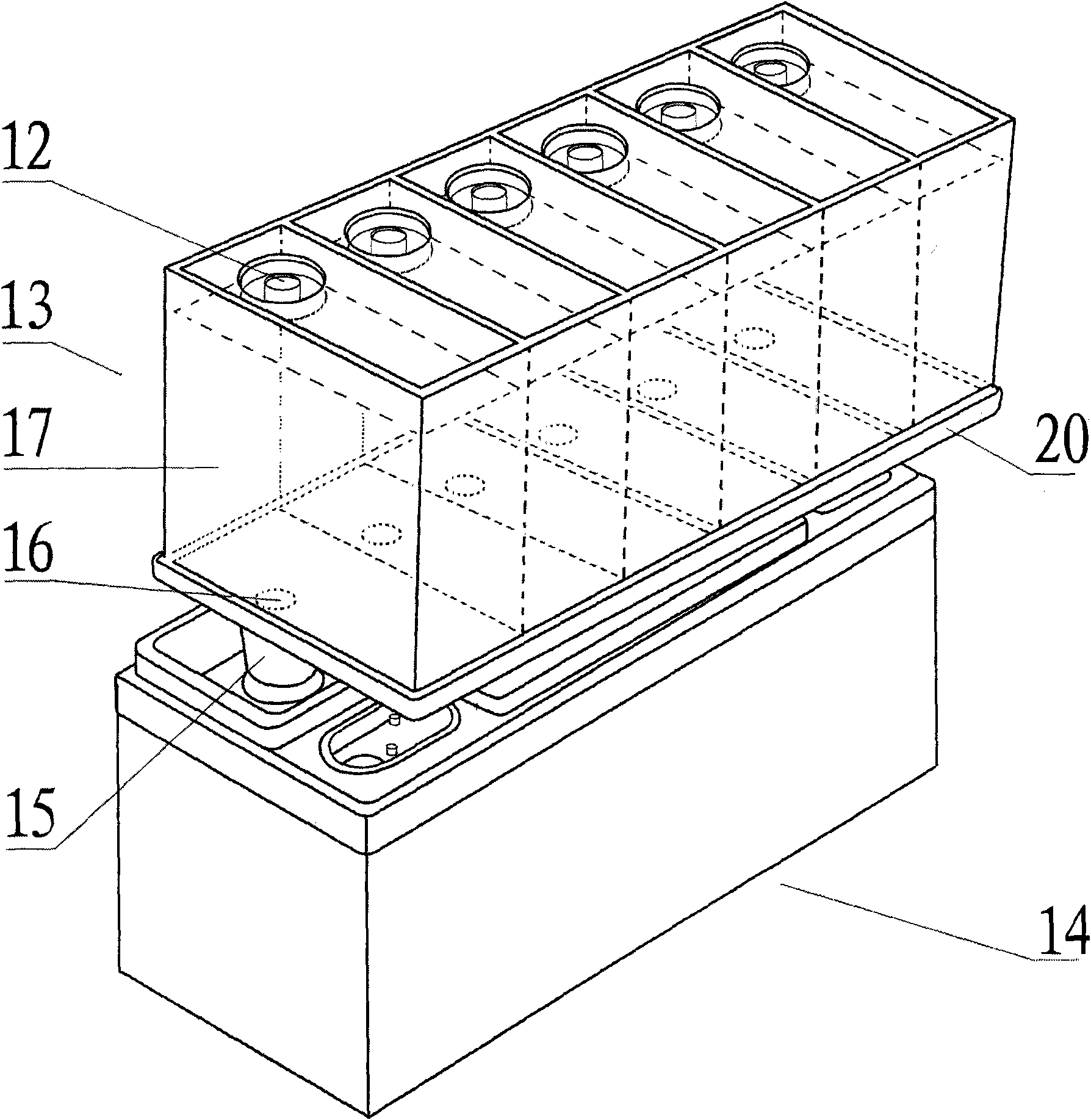
[0023] The liquid storage tank 13 is composed of a plurality of tank bodies 17. The tank bodies 17 are divided into "one" shapes and connected together. The upper end of the tank body 17 is provided with an acid inlet nozzle 12. The lower end of the portion is bonded and fixed to the upper end of the base 20. The acid inlet mouth 12 and the acid inlet hole 16 are in the same core position. Each of the acid inlet holes 16 is set at the bottommost position on the upper plane of the bottom platform 20 , so that the acid liquid can flow into the acid inlet holes 16 naturally. Four limit legs 19 are also provided on the lower part of the base 20 to support between the liquid storage tank 13 and the battery 14, so that the glue nozzle 15 can be normally stressed.

Example Embodiment

[0024] Example 2

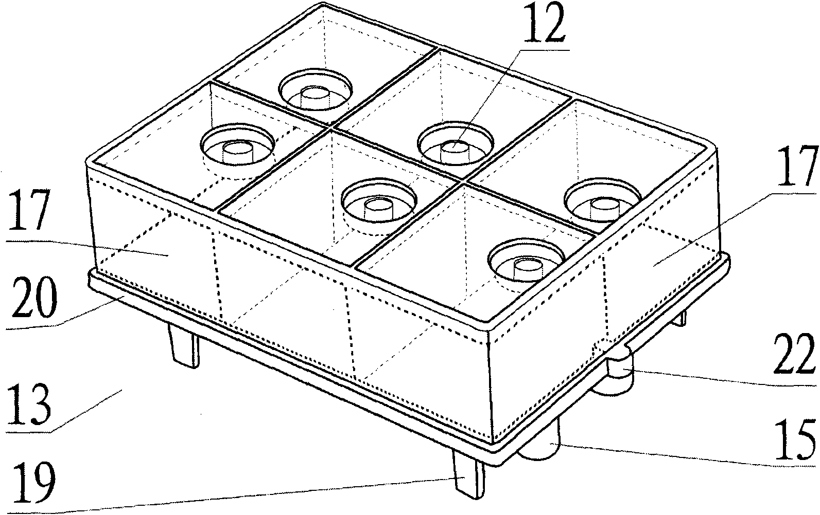
[0025] Liquid storage tank 13 is made up of a plurality of tank bodies 17, and described tank body 17 is arranged in two rows, and acid inlet nozzle 12 and glue nozzle mouth 18 are arranged on the inner side of each tank body 17, in order to make tank body 17 and bottom platform 20 is oriented in the direction of bonding, and an orientation platform 22 is arranged in the middle of one side of the bottom platform 20 . The acid inlet mouth 12 and the acid inlet hole 16 are in the same core position. Each of the acid inlet holes 16 is arranged at the bottom position of the upper plane of the bottom platform 20, so that the acid liquid can naturally flow into the acid inlet holes 16. Viewed from the back side of the bottom platform 20, because the acid inlet holes 16 are arranged on the bottom The bottommost position of the plane on the platform 20, so there is a funnel-shaped liquid leakage protrusion 21 at the bottom of the base platform 20, and the mouth of ...


PUM


Abstract

The invention relates to a formation liquid storage tank of quantitative acid dosing and charging of a battery, comprising an acid filling nozzle on an acid filling machine and the battery. The invention is characterized in that: a liquid storage structure is arranged between the acid filling nozzle and the battery. The acid filling nozzle is connected with an acid feeding nozzle at the upper part of the liquid storage tank when in filling acid; the liquid storage tank comprises at least one tank body. The tank bodies are distributed in a shape of a horizontal line or are arranged by two lines or multiple lines and connected together; the upper end of the tank body is provided with the acid feeding nozzle; and the lower end of the edge part of the tank body is fixedly bonded with the upper end of a bottom platform. The bottom part of the bottom platform is a liquid-leaking boss with the shape of a hopper; and the mouth of the liquid-leaking boss is connected with a rubber nozzle in an inserting mode. The invention has fast working speed, low fault rate, precise quantization and no liquid leakage, can solve the technical difficulty needing secondary liquid supplementation by once quantization after adding the liquid storage tank on the upper part of the battery, and simultaneously improves the quality of the battery.

Description

technical field [0001] The invention relates to a liquid storage tank, in particular to a liquid storage tank for battery quantitative charging and charging, which belongs to the acid-adding liquid storage tank used in the battery automatic quantitative acid filling machine. Background technique [0002] At present, the known battery automatic quantitative acid filling machine uses an adjustable measuring cup to determine the amount of acid to be added. The user can adjust the depth of the adjustment rod plug on the top of the acid filling machine in the quantitative cup to achieve quantitative changes. Each adjustment rod Only the amount of acid filling can be changed for each single channel without affecting each other. If the adjustment range cannot meet the requirements of acid addition, the user can replace the corresponding quantitative cup according to actual needs to achieve quantitative acid filling. During acid filling, There will be a small amount of acid flow to ...

Claims


Application Information

Patent Timeline
IPC IPC(8): H01M2/36H01M10/12H01M10/44H01M50/673
CPCY02E60/126Y02E60/10Y02P70/50
Inventor 王金铎
Owner 王金铎
Why Eureka
Try Eureka