
A full-automatic pin insertion device of a fan stator

A pin insertion device and a fully automatic technology, applied in the field of fully automatic pin insertion devices, can solve the problems of low production efficiency, labor and time-consuming, high production cost, etc., so as to avoid labor costs, work quickly, and improve work efficiency. The effect of efficiency

Pending Publication Date: 2018-12-18
苏州泉奇电子科技有限公司
View PDF0 Cites 0 Cited by
  • Summary
  • Abstract
  • Description
  • Claims
  • Application Information

AI Technical Summary

Problems solved by technology

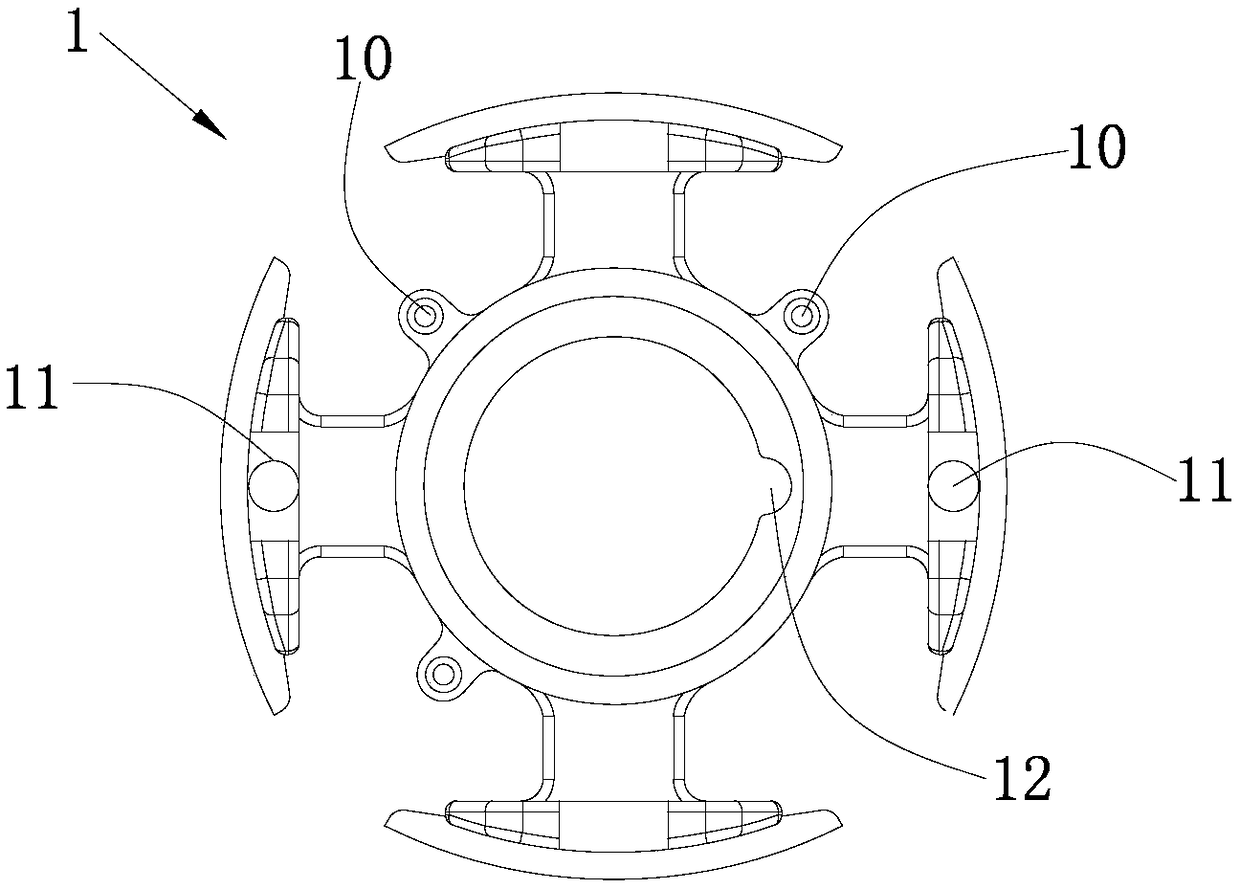
[0002] Pin insertion machine is also called PIN insertion machine and PIN needle machine equipment. PIN needle is a metal substance used to complete the conductive transmission of electrical signals in connectors. Therefore, PIN needles are widely used in electrical equipment; there is a computer CPU The fan stator used for cooling fans, in the prior art, the fan stator needs to insert three needles on the circumference, and it has the front and back sides, and the pins need to be inserted from the front with the pinholes, that is, in the pin insertion machine. Before inserting the pins, the fan stator needs to be put into the machine with the front side up and in a fixed orientation; at present, before the fan stator enters the pin insertion machine, the fan stator is manually turned upside down and placed in the The fixed direction is put into the pin insertion machine, so it is very labor-intensive and time-consuming, the production efficiency is extremely low, and the assembly quality cannot be guaranteed. production costs remain high

Method used


Image

  • A full-automatic pin insertion device of a fan stator
  • A full-automatic pin insertion device of a fan stator
  • A full-automatic pin insertion device of a fan stator

Examples


Embodiment Construction

[0025] The present invention will be described in further detail below in conjunction with the accompanying drawings and specific embodiments.

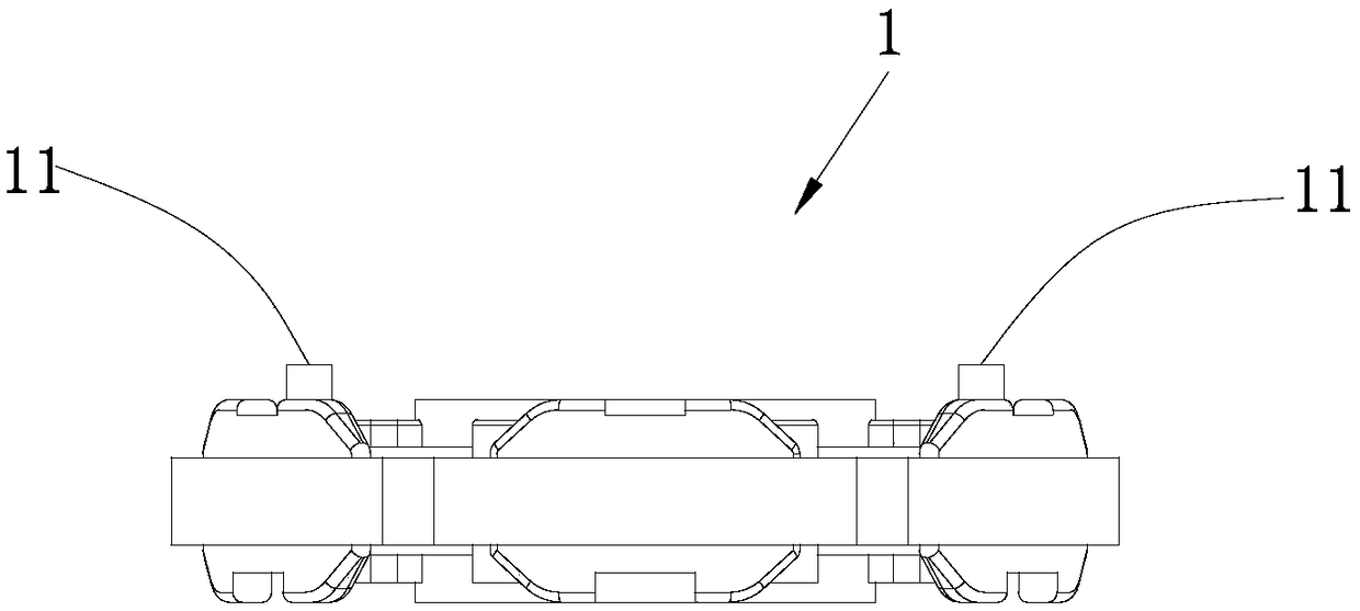
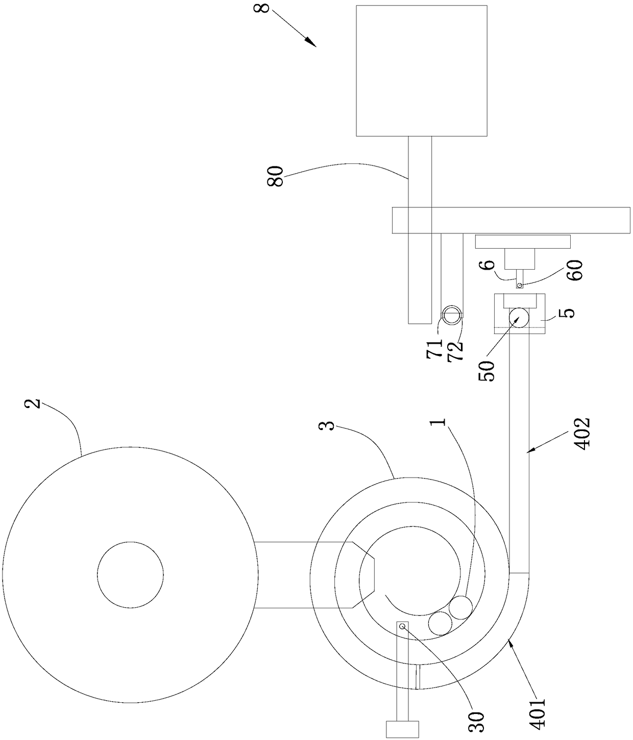
[0026] Such as figure 1 and Figure 6As shown, a fully automatic pin insertion device for a fan stator 1, the fan stator 1 has opposite first and second sides, and has a first placement direction and a second placement direction perpendicular to each other, the first side is provided with pins hole 10 (for each fan stator 1, three needles need to be inserted into the three pinholes 10 respectively), the fully automatic needle insertion device includes a needle insertion machine, a supply mechanism for orderly supplying the fan stator 1 to the needle insertion machine, and supply The mechanism includes a frame 100, a supply hopper arranged on the frame 100 for holding fan stators 1 in batches, and a surface-fixing mechanism arranged on the frame 100 for sequentially positioning the fan stators 1 on the first side. 1. An orientation m...


PUM


Abstract

The invention relates to a full-automatic pin insertion device of a fan stator, the fan stator has opposite first and second side faces, and has a first placement direction and a second placement direction perpendicular to each other, the first side face is provided with a pinhole, the full-automatic pin insertion device comprises a pin insertion machine, a supply mechanism for an orderly supply of a fan stator to a pin insertion machine, the supply mechanism comprises a rack, a feed hopper arranged on the rack for storing fan stators in batches, a surface fixing mechanism arranged on the rackfor fixing the fan stators on the first side in sequence, and an orientation mechanism arranged on the rack for directing the fan stators in the first placement direction in sequence. The fully automatic pin insertion device of the fan stator of the invention avoids putting the fan stator into the pin insertion machine with a correct posture after checking one by one manually in the prior art, avoids the expenditure of labor cost, also enables the pin insertion machine to work more quickly, and greatly improves the working efficiency.

Description

technical field [0001] The invention relates to a fully automatic pin insertion device for a fan stator. Background technique [0002] Pin insertion machine is also called PIN insertion machine and PIN needle machine equipment. PIN needle is a metal substance used to complete the conductive transmission of electrical signals in connectors. Therefore, PIN needles are widely used in electrical equipment; there is a computer CPU The fan stator used for cooling fans, in the prior art, the fan stator needs to insert three needles on the circumference, and it has the front and back sides, and the pins need to be inserted from the front with the pinholes, that is, in the pin insertion machine. Before inserting the pins, the fan stator needs to be put into the machine with the front side up and in a fixed orientation; at present, before the fan stator enters the pin insertion machine, the fan stator is manually turned upside down and placed in the The fixed direction is put into th...

Claims


Application Information

Patent Timeline
IPC IPC(8): H01R43/20
CPCH01R43/20
Inventor 吴滔
Owner 苏州泉奇电子科技有限公司
Learn More