Backlight driving circuit

A backlight drive circuit, electrical connection technology, applied in the direction of instruments, static indicators, etc., can solve the problem of high sound wave noise, and achieve the effect of reducing sound wave noise

Inactive Publication Date: 2011-06-15
INNOCOM TECH (SHENZHEN) CO LTD +1
View PDF0 Cites 0 Cited by
  • Summary
  • Abstract
  • Description
  • Claims
  • Application Information

AI Technical Summary

Problems solved by technology

[0005] In order to solve the problem of high acoustic noise in the prior art backlight drive circuit, it is necessary to provide a backlight drive circuit with low acoustic noise

Method used


Image

  • Backlight driving circuit
  • Backlight driving circuit
  • Backlight driving circuit

Examples


Embodiment Construction

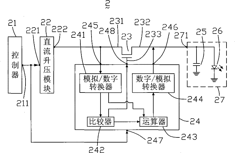
[0013] see figure 2 , is a schematic diagram of the circuit structure of the first embodiment of the backlight driving circuit of the present invention. The backlight driving circuit 2 includes a controller 21 , a DC boost module 22 , a switch assembly 23 , a voltage signal processor 24 and a load 27 .

[0014] The controller 21 includes a control signal output terminal 211 . The controller 21 generates a pulse signal and outputs it from the control signal output terminal 211 .

[0015] The DC boost module 22 includes a control signal input end 221 and an output end 222 . The control signal input end 221 is electrically connected to the control signal output end 211 of the controller 21 .

[0016] The switch element 23 includes a source terminal 231 , a drain terminal 232 and a gate terminal 233 . The source terminal 231 is electrically connected to the output terminal 222 of the DC boost module 22 .

[0017] The load 27 includes a driving voltage input terminal 271 . T...


PUM


Abstract

The invention relates to a backlight driving circuit which comprises a switch assembly, a load comprising a filter capacitor and a light source connected in parallel, a controller, a direct-current boost module and a voltage signal processor. The controller generates and outputs a control signal, and the direct-current boost module receives the control signal and correspondingly outputs a voltage signal to drive the load through the switch assembly. The voltage signal processor detects the voltage signal outputted by the direct-current boost module, and when the ripple of the voltage signal is smaller than a certain default, the switch assembly is conducted by the voltage signal processor; when the ripple of the voltage signal is greater than the certain default, the switch assembly is disconnected by the voltage signal processor, and the voltage signal is converted into a voltage signal with smaller ripples to drive the load.

Description

technical field [0001] The invention relates to a backlight driving circuit. Background technique [0002] Liquid crystal display devices are widely used in mobile phones, personal digital assistants, and portable digital video disc players (Digital Video Disc, DVD), laptops and TVs. However, since the liquid crystal display panel itself does not have luminous properties, it usually requires a backlight module to achieve the display effect. A backlight module usually includes a backlight driving circuit. [0003] see figure 1 , is a schematic diagram of the circuit structure of a prior art backlight driving circuit. The backlight driving circuit 1 includes a controller 11 , a DC boost module 12 , a filter capacitor 13 and a light source 14 . The light source 14 is a light emitting diode. The controller 11 includes an output terminal (not marked), the output terminal outputs a pulse signal to the DC boost module 12, and the DC boost module 12 generates a frequency equal...

Claims


Application Information

Patent Timeline
Patent Type & Authority Patents(China)
IPC IPC(8): G09G3/34G09G3/36
Inventor 符占伟
Owner INNOCOM TECH (SHENZHEN) CO LTD
Why Eureka
Try Eureka