Magnet system for a magnetic resonance imaging system

A magnetic resonance imaging and magnet technology, which is applied in the field of magnet systems and gradient systems of dental and limb MRI scanners, and can solve problems such as acoustic noise and limiting the space for assembling gradient coils.

Pending Publication Date: 2021-10-22
SIEMENS HEALTHCARE GMBH
View PDF1 Cites 0 Cited by
  • Summary
  • Abstract
  • Description
  • Claims
  • Application Information

AI Technical Summary

Problems solved by technology

However, usually the shape of the elementary field severely limits the space available for assembling gradient coils around the examination region
Since the gradient coils are very close to the field of view (FOV, the field of view) and the gradient coil size is limited by the need to keep the magnet size as small as possible, the achievable linearity of the gradient field over the extent of the imaging area yields question
[0010] Another serious disadvantage of the known scanner architecture is the acoustic noise generated by the gradient coils during the measurement

Method used


Image

  • Magnet system for a magnetic resonance imaging system
  • Magnet system for a magnetic resonance imaging system
  • Magnet system for a magnetic resonance imaging system

Examples


Embodiment Construction

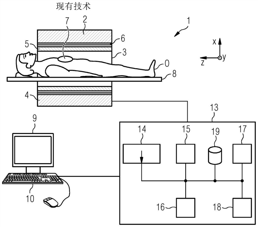
[0086] figure 1 A schematic representation of a magnetic resonance imaging system 1 ("MRI system") is shown. The MRI system 1 includes an actual magnetic resonance scanner (data acquisition unit) 2 with an examination space 3 or a patient tunnel, a patient or a tester is located on a drive bed 8 in the examination space 3 or a patient tunnel, and the actual examination object O is located on the drive bed middle.

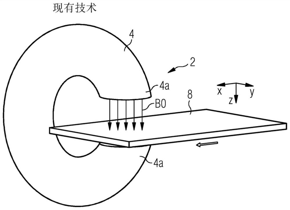
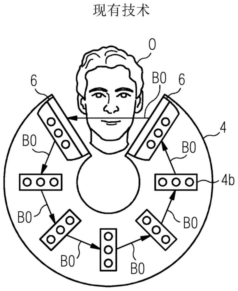
[0087] A magnetic resonance scanner 2 is typically equipped with a basic field magnet system 4 , a gradient system 6 and an RF transmit antenna system 5 and an RF receive antenna system 7 . In the exemplary embodiment shown, the RF transmit antenna system 5 is a whole-body coil permanently installed in the magnetic resonance scanner 2, whereas the RF receive antenna system 7 is formed to A local coil (represented here only by a single local coil) arranged on the patient or test object. In principle, however, whole body coils can also be used as RF receiving anten...


PUM


Abstract

The invention describes a magnet system for a magnetic resonance imaging system (1) comprising a basic field magnet (4) and a gradient system (6), wherein coils of the gradient system (6) are positioned outside the area of a predefined basic magnetic field (B0) of the basic field magnet (4). The invention further describes an according gradient system and a magnetic resonance imaging system with such magnet system.

Description

technical field [0001] The present invention describes a magnet system, preferably a gradient system, for magnetic resonance imaging (MRI), especially for dental and limb MRI scanners. Background technique [0002] The principles of magnetic resonance imaging ("MRI") have been used for imaging and other measurements for over forty years. Briefly, for this purpose, the examination object is positioned in a magnetic resonance (MR) scanner in a relatively strong and uniform static magnetic field, also called the B0 field, which has a field strength of 0.2T to 7T such that The object's nuclear spins are oriented along static magnetic field lines. In order to trigger nuclear spin resonance, a high-frequency excitation pulse (HF pulse) is irradiated onto the examination object. The measured nuclear spin resonance is called k-space data, and it is used for reconstruction of MR images or calculation of spectral data. [0003] To spatially encode the measurement data, a dynamicall...

Claims


Application Information

Patent Timeline
Patent Type & Authority Applications(China)
IPC IPC(8): G01R33/385G01R33/38G01R33/34G01R33/44
CPCG01R33/385G01R33/34G01R33/38G01R33/44G01R33/3806G01R33/3858G01R33/3808A61B5/055A61B5/4547G01R33/3854
Inventor 赖纳·基尔施斯特凡·波佩斯库
Owner SIEMENS HEALTHCARE GMBH
Why Eureka
Try Eureka