
Liquid discharging device and method of controlling the liquid discharging device

A technology of liquid discharge and liquid discharge head, which is applied in printing and other directions to achieve the effect of preventing enlargement

Inactive Publication Date: 2009-12-02
SONY CORP
View PDF1 Cites 6 Cited by
  • Summary
  • Abstract
  • Description
  • Claims
  • Application Information

AI Technical Summary

Problems solved by technology

[0007] However, if Figure 16B As shown, when the ink discharge surface 121 has a step, the rubber blade 141 cannot be in contact with the corner of the step.

Method used


Image

  • Liquid discharging device and method of controlling the liquid discharging device
  • Liquid discharging device and method of controlling the liquid discharging device
  • Liquid discharging device and method of controlling the liquid discharging device

Examples


Embodiment Construction

[0040] Embodiments of the present invention are described below with reference to the drawings.

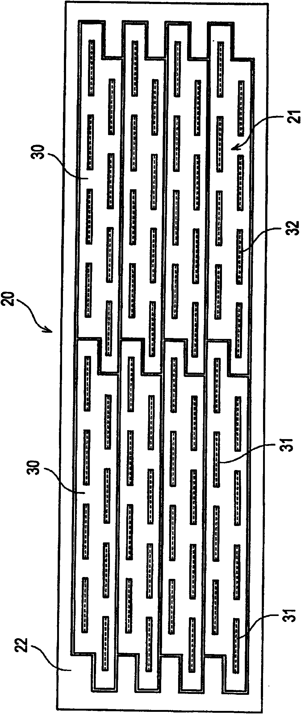
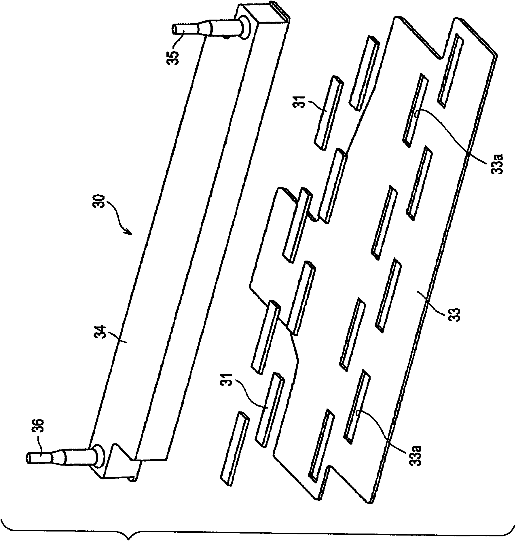
[0041] In the following embodiments, the inkjet printer 10 in which the discharged liquid is ink is used as an exemplary liquid discharge device according to an embodiment of the present invention. The inkjet printer 10 is a line type inkjet printer including a line head 20 and is a full-color inkjet printer in which the line head 20 (corresponding to the liquid discharge head in the present invention) is set to coincide with a printing width such as A4 size).

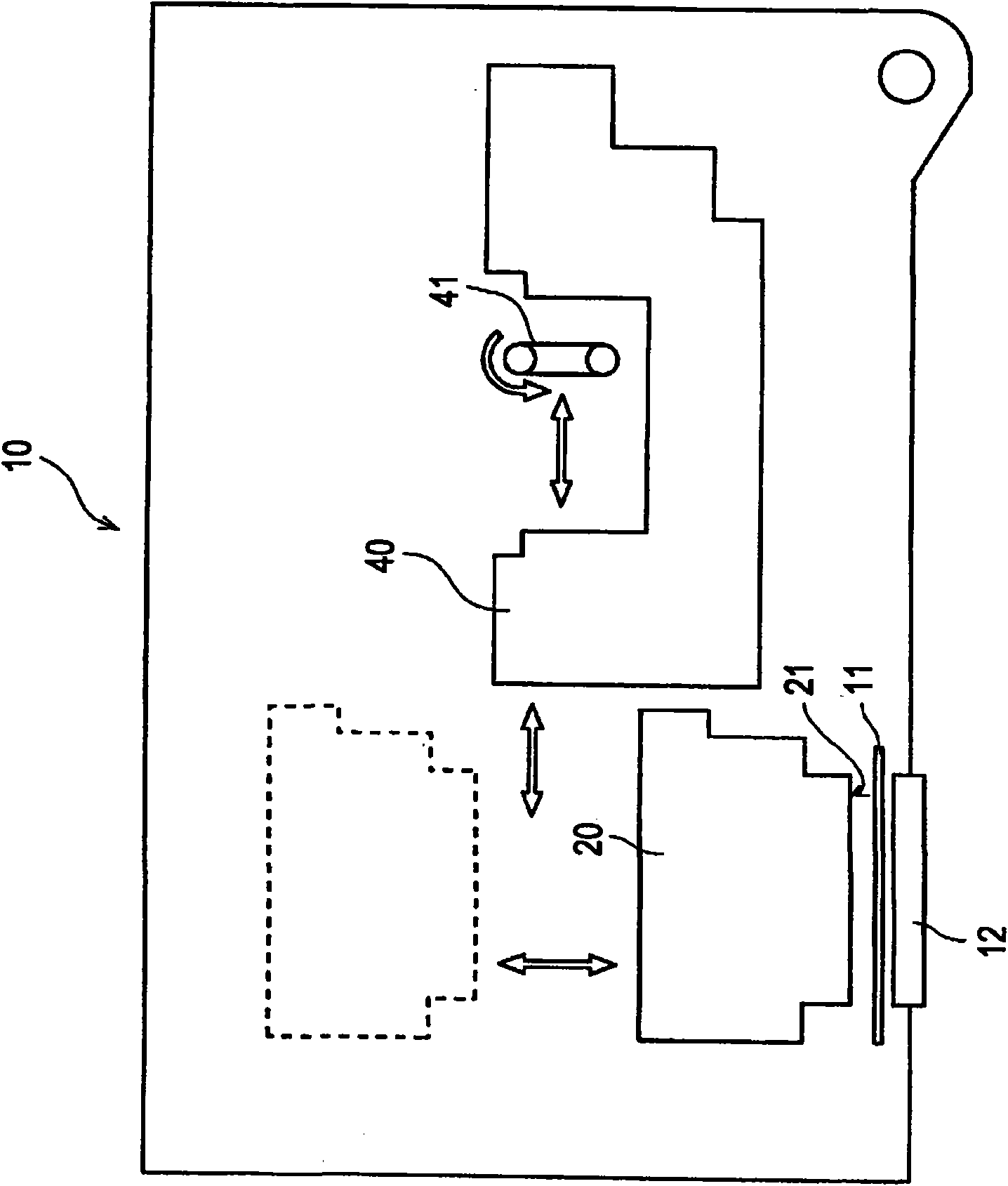
[0042] figure 1 is a schematic diagram of the entire structure of the inkjet printer 10 according to the embodiment.

[0043] Such as figure 1 As shown, the inkjet printer 10 includes a print station 11 , a line printhead 20 , a printhead cap 12 and a cleaning device 40 . The printing table 11 supports recording paper fed by a paper feeding section (not shown) substantially in parallel. The print head 20 discharges ...


PUM


Abstract

The present invention relates to a liquid discharging device and method of controlling the liquid discharging device. The liquid discharging device includes a plurality of nozzles for discharging liquid, a liquid discharging head having a nozzle row in which each of the nozzles is arranged in one direction, an endless cleaning belt for cleaning a liquid discharging surface of the liquid discharging head, an installation roller on which the cleaning belt is rotatably installed, a supporting frame that supports the installation roller so that a widthwise direction of the cleaning belt is set at an angle with the arrangement direction of the nozzles, and so that the cleaning belt positioned around the installation roller is capable of contacting the liquid discharging surface, a moving unit that moves the supporting frame in the arrangement direction of the nozzles, and a rotationally driving unit that rotationally drives the installation roller.

Description

technical field [0001] The present invention relates to a liquid discharge device which cleans the surface of a liquid discharge head having nozzle arrays for discharging liquid, and to a method of controlling the liquid discharge device. More specifically, the present invention relates to a technique capable of making it possible to recover cleaning capability without reducing cleaning capability during cleaning operation and preventing the device from becoming larger even when the number of nozzle rows is increased. Background technique [0002] A liquid discharge device such as an inkjet printer discharges liquid from a plurality of nozzles of a liquid discharge head and forms, for example, an image on recording paper. Therefore, when the liquid discharge surface of the liquid discharge head is contaminated or when, for example, an image is formed while liquid, dust, etc. adhere to the liquid discharge surface, the print quality is lowered. Specifically, for a full-color...

Claims


Application Information

Patent Timeline
Patent Type & Authority Applications(China)
IPC IPC(8): B41J2/165
CPCB41J2/16535B41J2/16585
Inventor 山口俊二
Owner SONY CORP
Learn More