Large-flow ultraviolet fluid sterilizer

An ultraviolet disinfection and ultraviolet technology, which is applied in chemical instruments and methods, light water/sewage treatment, water/sewage treatment, etc. and other problems, to achieve the effect of improving pressure tolerance, improving disinfection effect, and improving utilization rate

Active Publication Date: 2009-12-02
FUJIAN NEWLAND ENTECH CO LTD
View PDF0 Cites 5 Cited by
  • Summary
  • Abstract
  • Description
  • Claims
  • Application Information

AI Technical Summary

Problems solved by technology

[0002] From the perspective of current technology, the main cavity of the existing closed ultraviolet sterilizer is usually cylindrical, with a water inlet and outlet on the wall of the cylinder, and an ultraviolet lamp tube is installed at the end of the cylinder, and water flows into the cavity from the water inlet. The body flows out from the water outlet after being irradiated by ultraviolet rays. Since the water inlet and outlet are set on the wall of the cylinder, it is necessary to open on the wall of the cylinder, and then install the water inlet and outlet to connect with the water supply and water outlet pipes, and the water flows from the opening on the cylinder wall. When entering and exiting the cavity, the water flow pressure on the cylinder wall increases, especially when dealing with large flow fluids, it is easy to produce a short circuit of the water flow around the cylinder wall, that is, part of the water flow close to the cylinder wall directly flows out of the cavity without sufficient disinfection, shortening the flow acceptance. The distance of ultraviolet radiation reduces the dose of ultraviolet radiation to the water and reduces the disinfection effect, and there is a large difference in the head of the water inlet and outlet, the head loss of the water flow is too large, and the pressure of the disinfection chamber is small. Therefore, a method that can avoid Ultraviolet disinfection device with short circuit of water flow, high pressure resistance of disinfection chamber and small head loss to meet the demand

Method used


Image

  • Large-flow ultraviolet fluid sterilizer
  • Large-flow ultraviolet fluid sterilizer
  • Large-flow ultraviolet fluid sterilizer

Examples


Embodiment Construction

[0023] The embodiments are described in detail below in conjunction with the accompanying drawings.

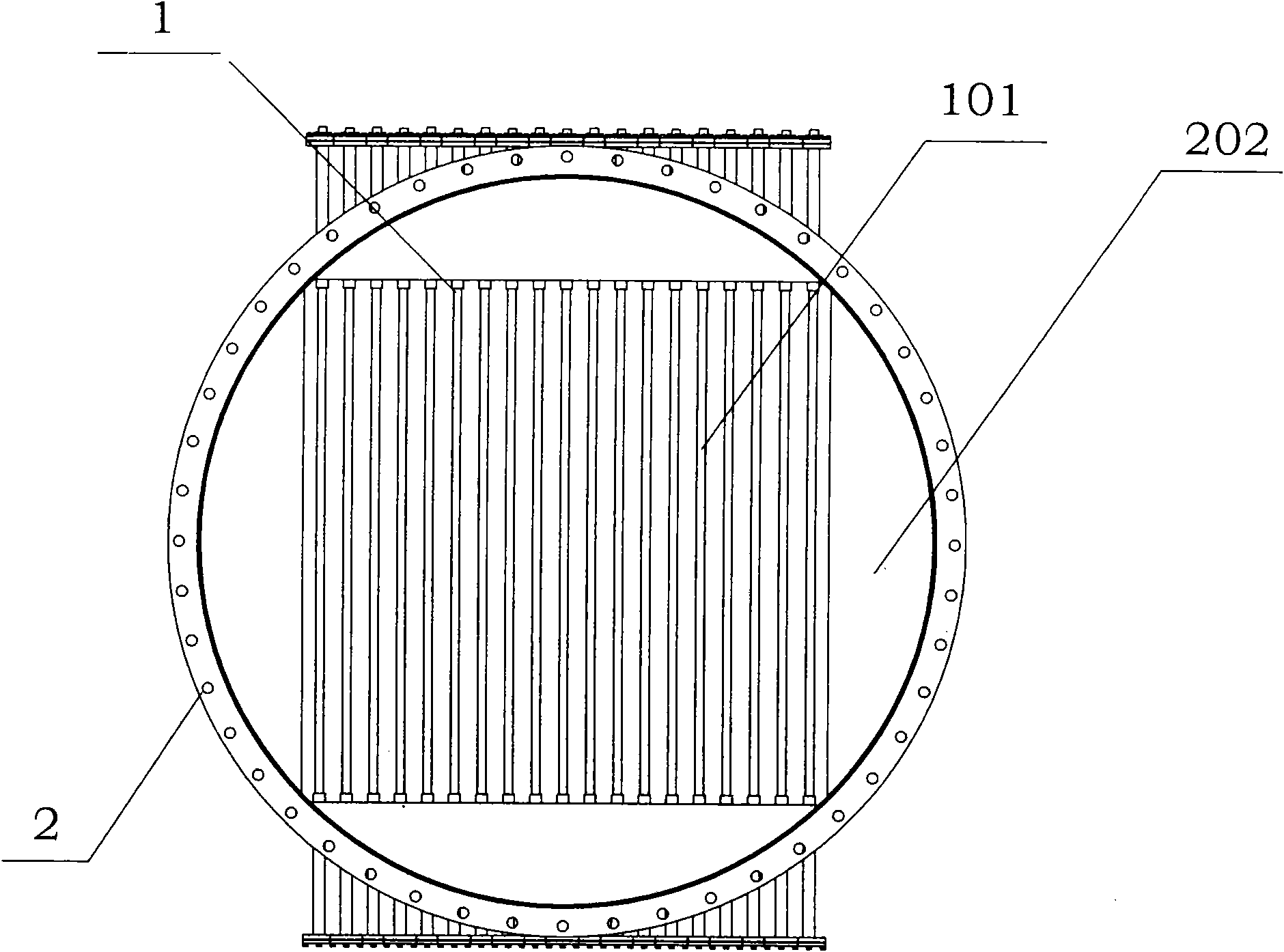
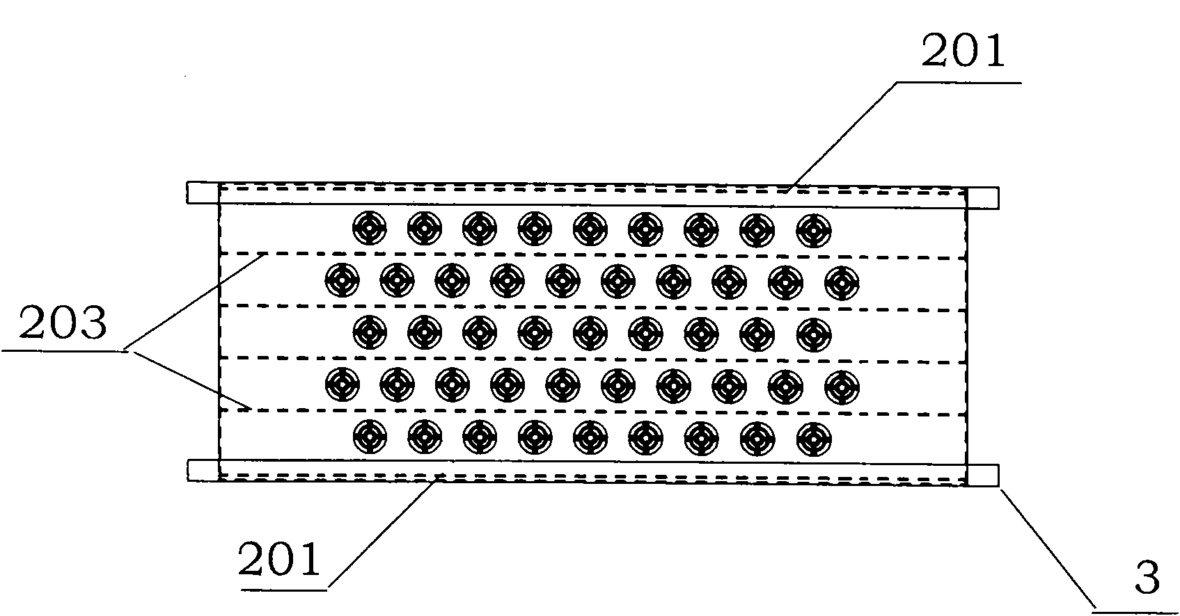
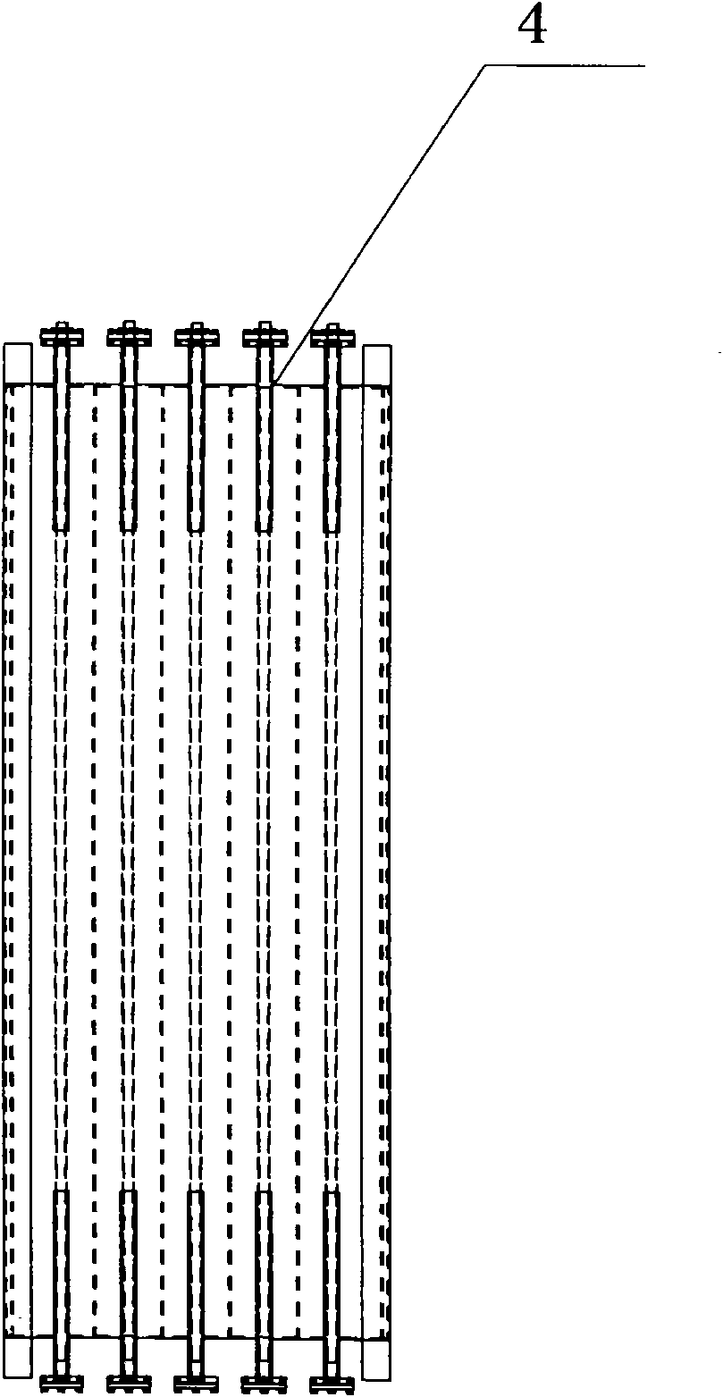
[0024] Such as figure 1 , 2 . The large-flow ultraviolet fluid sterilizer shown in 3 adopts a modular structure, each module includes at least one ultraviolet disinfection module 1 and an installation fixture 2 for the ultraviolet disinfection module, and each ultraviolet disinfection module 1 includes at least one ultraviolet lamp tube 101, the main body of the installation and fixing device 2 is a pipeline through which the sterilized fluid can pass, and several ultraviolet disinfection module installation holes 4 are arranged on the pipeline wall, and one or two end faces 201 of the installation and fixing device 2 are provided with The baffle plate 202 extending from the outer periphery of the end surface toward the center of the end surface, and the end surface 201 where the baffle plate 202 is located has a water outlet 203 for the fluid to be sterilized to pass through...


PUM


Abstract

The invention relates to a large-flow ultraviolet fluid sterilizer comprising at least one ultraviolet sterilizing module and an installing and fixing device of the ultraviolet sterilizing module, wherein each ultraviolet sterilizing module at least comprises an ultraviolet lighting tube, a main body of the installing and fixing device is a pipeline which can be passed by sterilized fluid, a plurality of ultraviolet sterilizing module installing holes are arranged on the wall of the pipeline, baffle plates which extend to the center direction of the end surface from the periphery of the end surface are arranged on one or two end surfaces of the installing and fixing device, and water through holes which are passed by the sterilized fluid are arranged on the end surfaces of the baffle plates. The large-flow ultraviolet fluid sterilizer can be widely used for locations which need to sterilize fluid, such as water plants, pharmaceutical factories, food factories, beverage factories, and the like and can be also used for other fluid sterilization systems which need to be sterilized.

Description

Technical field: [0001] A large-flow ultraviolet fluid sterilizer of the invention belongs to the field of ultraviolet fluid disinfection. Background technique: [0002] From the perspective of current technology, the main cavity of the existing closed ultraviolet sterilizer is usually cylindrical, with a water inlet and outlet on the wall of the cylinder, and an ultraviolet lamp tube is installed at the end of the cylinder, and water flows into the cavity from the water inlet. The body flows out from the water outlet after being irradiated by ultraviolet rays. Since the water inlet and outlet are set on the wall of the cylinder, it is necessary to open on the wall of the cylinder, and then install the water inlet and outlet to connect with the water supply and water outlet pipes, and the water flows from the opening on the cylinder wall. When entering and exiting the cavity, the water flow pressure on the cylinder wall increases, especially when dealing with large flow flui...

Claims


Application Information

Patent Timeline
Patent Type & Authority Applications(China)
IPC IPC(8): C02F1/32
CPCC02F1/325C02F2201/3227C02F2201/328
Inventor 陈健韩闽毅
Owner FUJIAN NEWLAND ENTECH CO LTD
Why Eureka
Try Eureka