Lens group

A lens set and lens technology, applied in the field of lens sets, can solve the problems of reducing the production accuracy and deviation of finished products, increasing the difficulty of demolding the first lens 21 and the second lens 22, etc., so as to reduce the difficulty of demolding, reduce the height, The effect of improving image quality

Inactive Publication Date: 2009-12-02
HONG FU JIN PRECISION IND (SHENZHEN) CO LTD +1
View PDF0 Cites 8 Cited by
  • Summary
  • Abstract
  • Description
  • Claims
  • Application Information

AI Technical Summary

Problems solved by technology

However, if a longer distance is required between the first lens 21 and the second lens 22 to meet the design requirements, at this time, the length of the interlocking between the first boss 211 and the boss 221 needs to be increased, that is, the first boss 211 The height from the boss 221 will increase, thereby increasing the difficulty of demolding the first lens 21 and the second lens 22 during the molding process, reducing the manufacturing precision of the finished product, and making the first boss 211 and the boss 221 unable to accurately match after forming Mutual jamming may cause the optical axes of the assembled first lens 21 and second lens 22 to be out of alignment, resulting in a deviation, thereby affecting the imaging quality of the lens group

Method used


Image

  • Lens group
  • Lens group
  • Lens group

Examples


Embodiment Construction

[0011] The lens set provided by the embodiment of the technical solution will be further described in detail below with reference to the drawings and embodiments.

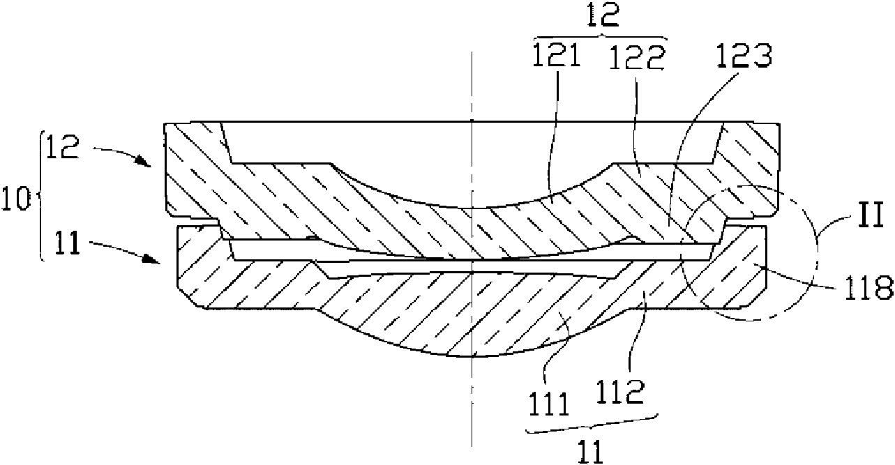
[0012] see figure 1 and figure 2 , the lens set 10 provided in this embodiment includes a first lens 11 and a second lens 12 assembled with the first lens 11 . Both the first lens 11 and the second lens 12 include an optical part located at the center of the lens and a fixing part located at the periphery of the lens for fixing the lens. The optical part is an effective optical imaging area, which is used to make the light beam pass through for imaging, while the fixing part is only used for fixing the lens and does not participate in the imaging.

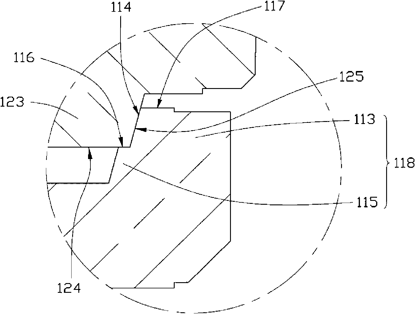
[0013] In this embodiment, the first lens 11 includes a first optical portion 111 and a first fixing portion 112 . A step 118 protruding outward from the first fixing part 112 is disposed on the periphery of the first lens 11 (ie, the first fixing part 112 ). In t...


PUM


Abstract

The invention provides a lens group, which comprises a first lens and a second lens, wherein both the first lens and the second lens comprise an optical part positioned in the center of a lens and a fixed part which is positioned on the circumference of the lens and is used for fixing the lens; the circumference of the first lens is provided with a bench, and the bench is provided with a first propping surface vertical to an optical axis of the first lens; and the circumference of the second lens is provided with a lug boss which is matched and clamped with the bench, and the lug boss is provided with a second propping surface which is far from the fixed part of the second lens, is vertical to an optical axis of the second lens, and is used for propping against the first propping surface.

Description

technical field [0001] The invention relates to the technical field of optical lens design, in particular to a lens group. Background technique [0002] In recent years, while people are pursuing the miniaturization of digital cameras, video cameras and mobile phones with camera functions, they have also put forward higher requirements for the image quality of the objects they shoot, that is, they hope that the images of the objects they shoot are clear. The imaging quality of an object largely depends on whether the optical axes of the lenses in the lens module are aligned during the assembly process. In the paper Zoom Lens Calibration For Wind Tunnel Measurements published by Alpheus W. Burner et al. at the Fourth Conference of SPIE System and Image Metrology (Videometrics IV) in 1995, it was revealed that the optical axes of the lenses in the lens module are not aligned. and the resulting impact. [0003] Such as image 3 As shown, a common lens assembly method in the p...

Claims


Application Information

Patent Timeline
Patent Type & Authority Applications(China)
IPC IPC(8): G02B7/02G02B7/04
CPCG02B9/04G02B13/001G02B7/021
Inventor 董才士
Owner HONG FU JIN PRECISION IND (SHENZHEN) CO LTD
Why Eureka
Try Eureka