Air flotation conveying device

A conveying device and air flotation technology, applied in transportation and packaging, thin material handling, winding strips, etc., can solve problems such as difficult to control the tension and flatness of the flexible circuit board 92, circuit damage, etc.

Inactive Publication Date: 2009-12-09
CONTREL TECH CO LTD
View PDF0 Cites 16 Cited by
  • Summary
  • Abstract
  • Description
  • Claims
  • Application Information

AI Technical Summary

Problems solved by technology

[0003] Generally speaking, the flexible circuit board must use external force to achieve a certain tension during the transportation process, so that the flexible circuit board has a certain degree of flatness, such as figure 1 As shown, the existing conveying device 90 utilizes several rollers 91 arranged crosswise, so that the flexible circuit board 92 can generate a certain tension during the conveying process, thereby making the flexible circuit board 92 have a certain flatness; but the flexible circuit board The surface 921 with the circuit on the top of 92 is easy to damage the circuit due to the pressure of contact. Therefore, the roller 91 has a certain pressure limit when conveying the flexible circuit board 92, and it is difficult to control the tension and flatness required by the flexible circuit board 92.

Method used


Image

  • Air flotation conveying device
  • Air flotation conveying device
  • Air flotation conveying device

Examples


Embodiment Construction

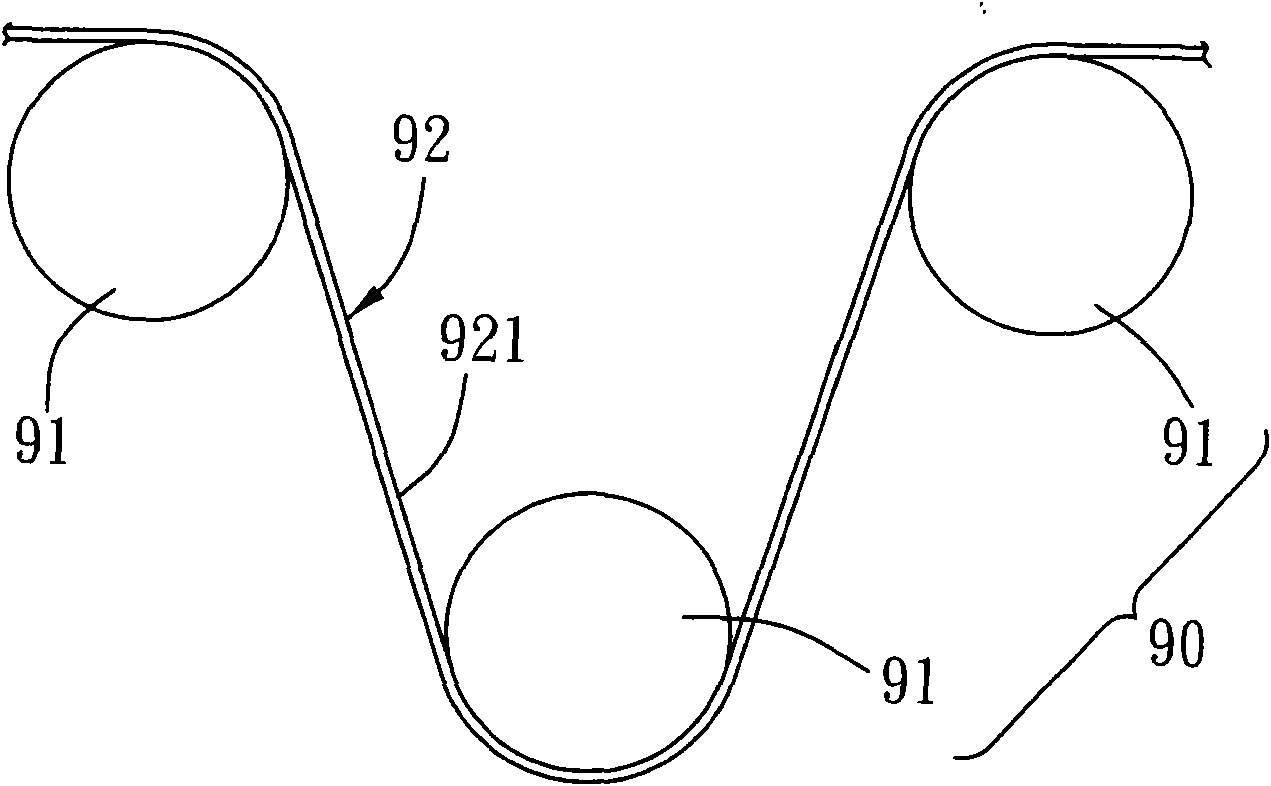
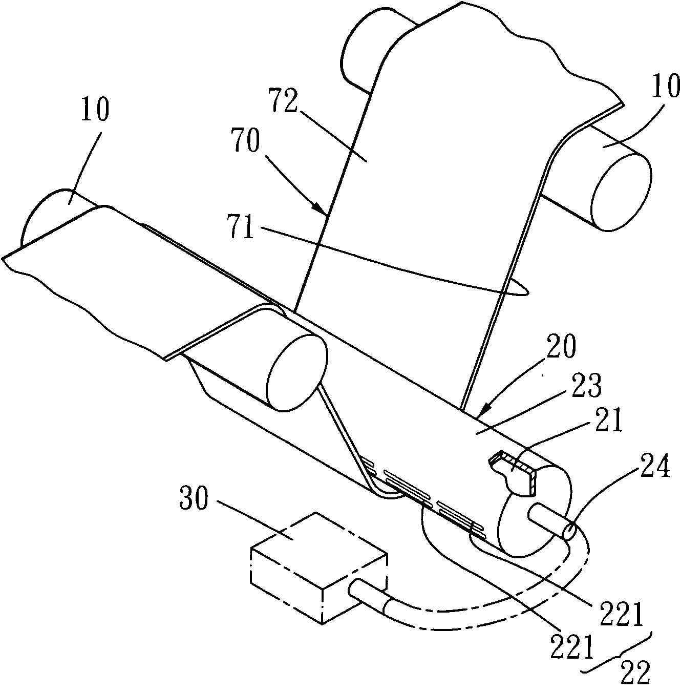
[0035] Such as figure 2 and image 3 As shown, the present invention is an air-floating conveying device, which includes at least two conveying shafts 10 and at least one air-floating conveying shaft 20, used to transport a curved and sheet-shaped object 70 to be tested to move;

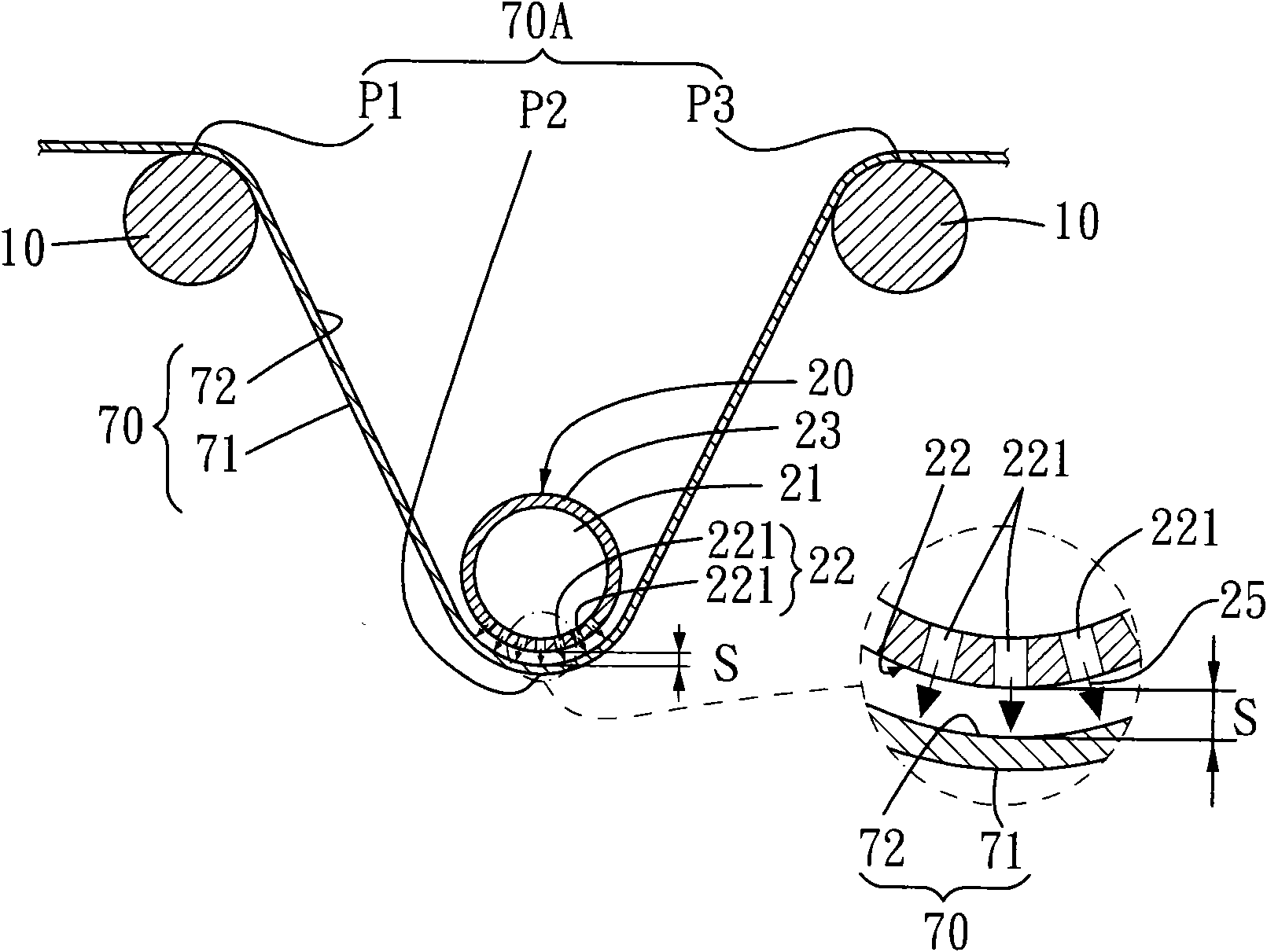
[0036] The object to be tested 70 has a contact surface 71 and a working surface 72; the conveying shaft 10 is in contact with the contact surface 71 of the object to be measured 70, and the air bearing conveying shaft 20 is adjacent to but not in contact with the object to be measured 70 and, the object to be tested 70 is limited by the air bearing conveying shaft 20 to form a curved section 70A between the two conveying shafts 10 (such as image 3 As shown, the bending section 70A is a range formed by a first contact point P1, a limiting point P2 and a second contact point P3);

[0037] The air-floating conveying shaft 20 has a gas storage space 21, a working part 22, a non-working part 23 and a...


PUM


Abstract

The invention relates to an air flotation conveying device which comprises at least two conveying shafts and at least one air flotation conveying shaft and is used for conveying a bent and approximately sheet object to be detected to move. The object to be detected is provided with a contact surface and an operating surface; the conveying shafts are contacted with a contact surface of the object to be detected while the air flotation conveying shaft is adjacent to and not contacted with the operating surface of the object to be detected; and the object to be detected is limited by the air flotation conveying shafts to form a bending section between the two conveying shafts. Each air flotation conveying shaft is provided with an air storage space, an operating part, a non-operating part and an air intake part, wherein the air storage space is used for storing high-pressure gas; the operating part is adjacent and faces toward the operating surface without contacting and is provided with a plurality of exhaust holes; and the air intake part is used for conveying the high-pressure gas to enter the air storage space and sending the high-pressure gas out by the plurality of exhaust holes of the operating part to form an air cushion layer, therefore, a predetermined space is generated between the operating surface of the object to be detected and the operating part of the air flotation conveying shafts. The invention has the protection of the specified surface and is capable of carrying out non-contact tension adjustment.

Description

technical field [0001] The invention relates to an air-floating conveying device, in particular to an air-floating conveying device with an air-floating conveying shaft. Background technique [0002] In recent years, the light, thin, and short design trends of consumer electronics have become the driving force for the growth of the flexible printed circuit board market; ), notebook computers are its main application markets. [0003] Generally speaking, the flexible circuit board must use external force to achieve a certain tension during the transportation process, so that the flexible circuit board has a certain degree of flatness, such as figure 1 As shown, the existing conveying device 90 utilizes several rollers 91 arranged crosswise, so that the flexible circuit board 92 can generate a certain tension during the conveying process, thereby making the flexible circuit board 92 have a certain flatness; but the flexible circuit board The surface 921 with the circuit on t...

Claims


Application Information

Patent Timeline
Patent Type & Authority Applications(China)
IPC IPC(8): B65H23/24B65H23/34B65H23/00B65H20/04
Inventor 苏荣瑞黄明鸿杜水年
Owner CONTREL TECH CO LTD
Why Eureka
Try Eureka