Light-emitting diode (LED) driving power supply

A LED drive and circuit technology, applied in the direction of electric light source, light source, lamp circuit layout, etc., can solve the problems of high-power LED drive power supply complexity, lack of stability and reliability, and low work efficiency, so as to suppress adverse effects and avoid adverse consequences , the effect of cost reduction

Inactive Publication Date: 2013-04-24
ZHONGSHAN YALESI ELECTRIC CO LTD
View PDF5 Cites 7 Cited by
  • Summary
  • Abstract
  • Description
  • Claims
  • Application Information

AI Technical Summary

Problems solved by technology

[0005] This traditional high-power LED drive power supply is relatively complex, and some of its components have the disadvantages of large volume, high power, high cost, and high failure rate, such as high-power MOS tubes, high-frequency transformers, recovery diodes, electrolytic capacitors, etc., making The entire circuit consumes a lot of energy, has low work efficiency, and at the same time has a high overall cost and lacks stability and reliability in use.

Method used


Image

  • Light-emitting diode (LED) driving power supply
  • Light-emitting diode (LED) driving power supply
  • Light-emitting diode (LED) driving power supply

Examples


Embodiment 1

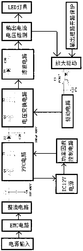
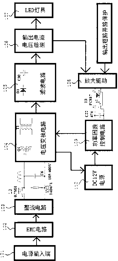
[0025] Such as figure 2 As shown, a LED drive power supply of the present invention includes a power input terminal 101, an EMC circuit 102, a rectifier circuit 103, a voltage conversion circuit 104, a filter circuit 105, an output current and voltage detection circuit 106, and an LED lamp 107 connected in sequence. . It also includes a constant current and constant voltage control circuit, including an amplifying drive 108 and a power factor control circuit 109, the input end of the amplifying drive 108 is connected to the output end of the output current voltage detection circuit 106, and the output end of the amplifying drive 108 is connected to the power factor control circuit 109 The input end of the power factor control circuit 109 is connected to the input end of the voltage conversion circuit 104 . At the same time, an inductor L3 and a piezoresistor YM3 are connected in series between the rectifier circuit 103 and the voltage conversion circuit 104, and the input te...

Embodiment 2

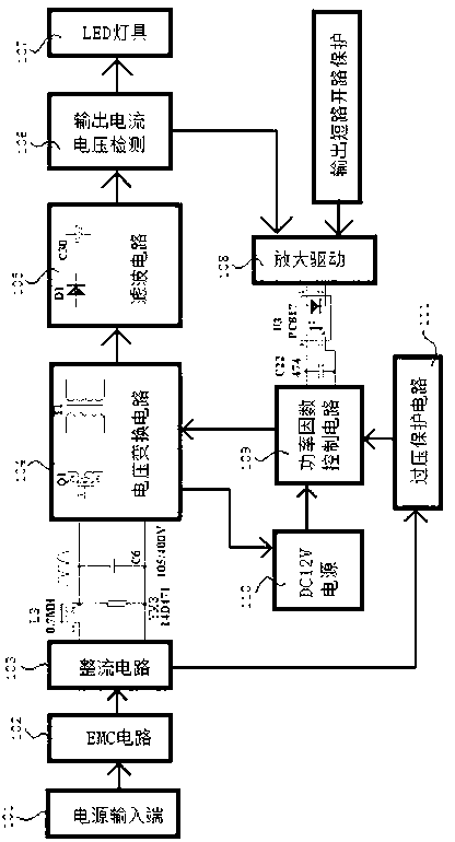
[0031] Such as image 3 As shown, the difference between this embodiment and Embodiment 1 is: in this embodiment, an overvoltage protection circuit 111 is connected between the rectification circuit 103 and the power factor control circuit 109, and the input terminal of the overvoltage protection circuit 111 It is connected with the output end of the rectification circuit 103 , and the output end of the overvoltage protection circuit 111 is connected with the input end of the power factor control circuit 109 . When the voltage of the rectifier circuit 103 is higher than a certain value, the overvoltage protection circuit 111 sends the signal to the power factor control circuit 109 to control and cut off the voltage conversion circuit 104; when the voltage returns to the normal range, the overvoltage protection circuit 111 sends the signal The output is sent to the power factor control circuit 109, and the voltage conversion circuit 104 is controlled to be turned on.

[0032] ...

Embodiment 3

[0034] Such as Figure 4 As shown, the difference between this embodiment and Embodiment 1 lies in that: in this embodiment, the input end of the amplifying driver 108 is connected with an over-temperature protection circuit 112 . When the temperature of the LED lamp 107 is too high, the over-temperature protection circuit 112 sends the signal to the amplifying driver 108, and the voltage fed back from the amplifying driver 108 to the power factor control circuit 109 increases, and then the power factor control circuit 109 makes the output control signal The duty cycle is reduced, and then the conduction time of the MOS transistor Q1 in the voltage conversion circuit 104 is controlled to be shortened, thereby forcibly reducing the output current, avoiding damage to the LED lamp due to excessive temperature, and further improving the stability and reliability of use.

[0035] Other structures are the same as in Embodiment 1.


PUM


Abstract

The invention relates to the light-emitting diode (LED) manufacturing field and provides a LED driving power supply. The LED driving power supply comprises a power input end, an electro magnetic compatibility (EMC) circuit, a rectifying circuit, a voltage conditioning circuit, a filtering circuit, an output current voltage detecting circuit and an LED lamp at the output end of the output current voltage detecting circuit, and further comprises a constant current and constant voltage controlling circuit, wherein the power input end, the EMC circuit, the rectifying circuit, the voltage conditioning circuit, the filtering circuit, the output current voltage detecting circuit and the LED lamp are connected in sequence, the constant current and constant voltage controlling circuit is connected with an output end of the output current voltage detecting circuit and an input end of the voltage conditioning circuit, an inductance and a piezoresistor are arranged between the rectifying circuit and the voltage conditioning circuit, the inductance is connected with the rectifying circuit and the voltage conditioning circuit in series, the piezoresistor is connected with the rectifying circuit and the voltage conditioning circuit in parallel, and the input end of the piezoresistor is connected with the output end of the inductance. The LED driving power supply has the advantages that elements with big sizes, high failure rates and high prices are greatly reduced, the structure is simple and reasonable, the cost is lowered and application is stable and reliable. The inductance is added between the rectifying circuit and the voltage conditioning circuit, so that undesirable effects due to the fact that different-mode signals transit to a power grid are restrained, meanwhile the piezoresistor is added, and thereby the ability of the power supply to reject outside surge is improved.

Description

technical field [0001] The invention relates to the field of LED manufacturing, and more specifically relates to a stable and reliable LED driving power supply with simple and reasonable structure, reduced cost. Background technique [0002] LED, light-emitting diode, is a semiconductor component that can convert electrical energy into light energy. It has the advantages of small size, low power consumption, long service life, environmental protection and durability, and is widely used in lighting fixtures, display screens, traffic lights, etc. field. [0003] Since the LED is a semiconductor device with sensitive characteristics and has negative temperature characteristics, it needs to be in a stable working state and protected during the application process, thus requiring an LED drive power supply. LEDs have very strict requirements on driving power, unlike ordinary incandescent bulbs, which can be directly connected to 220V AC mains. LED is driven by a low voltage of 2...

Claims


Application Information

Patent Timeline
Patent Type & Authority Applications(China)
IPC IPC(8): H05B37/02
Inventor 刘清祥李志民周瑜
Owner ZHONGSHAN YALESI ELECTRIC CO LTD
Why Eureka
Try Eureka