
Heating device

A technology for heating devices and terminals, which is applied in the direction of lighting devices, lighting and heating equipment, parts of lighting devices, etc., to achieve the effect of inhibiting the movement of the tube axis

Active Publication Date: 2013-06-26
USHIO DENKI KK
View PDF2 Cites 0 Cited by
  • Summary
  • Abstract
  • Description
  • Claims
  • Application Information

AI Technical Summary

Problems solved by technology

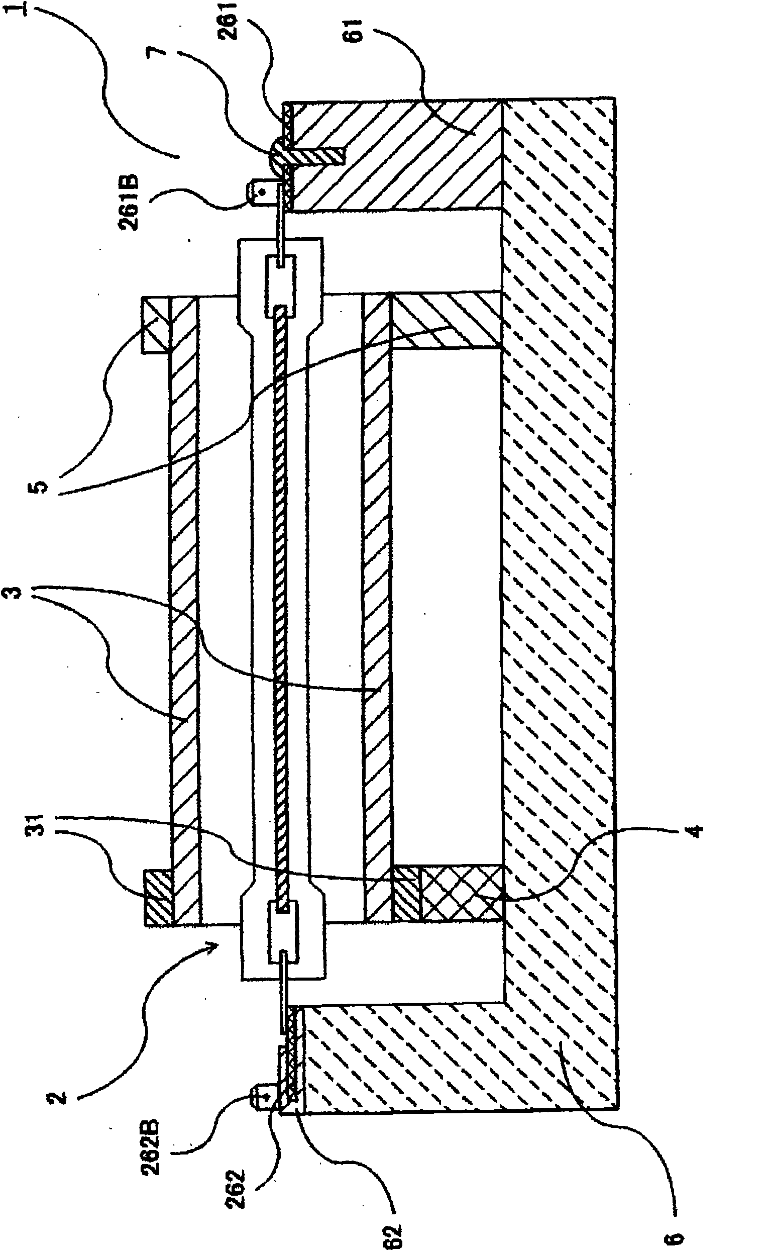
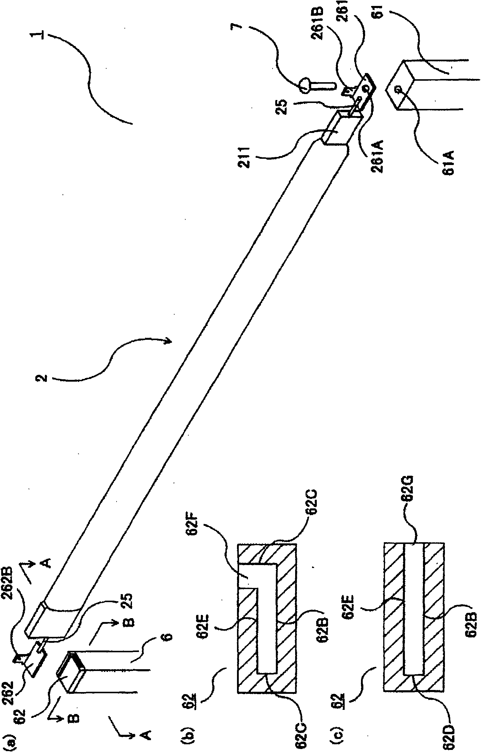
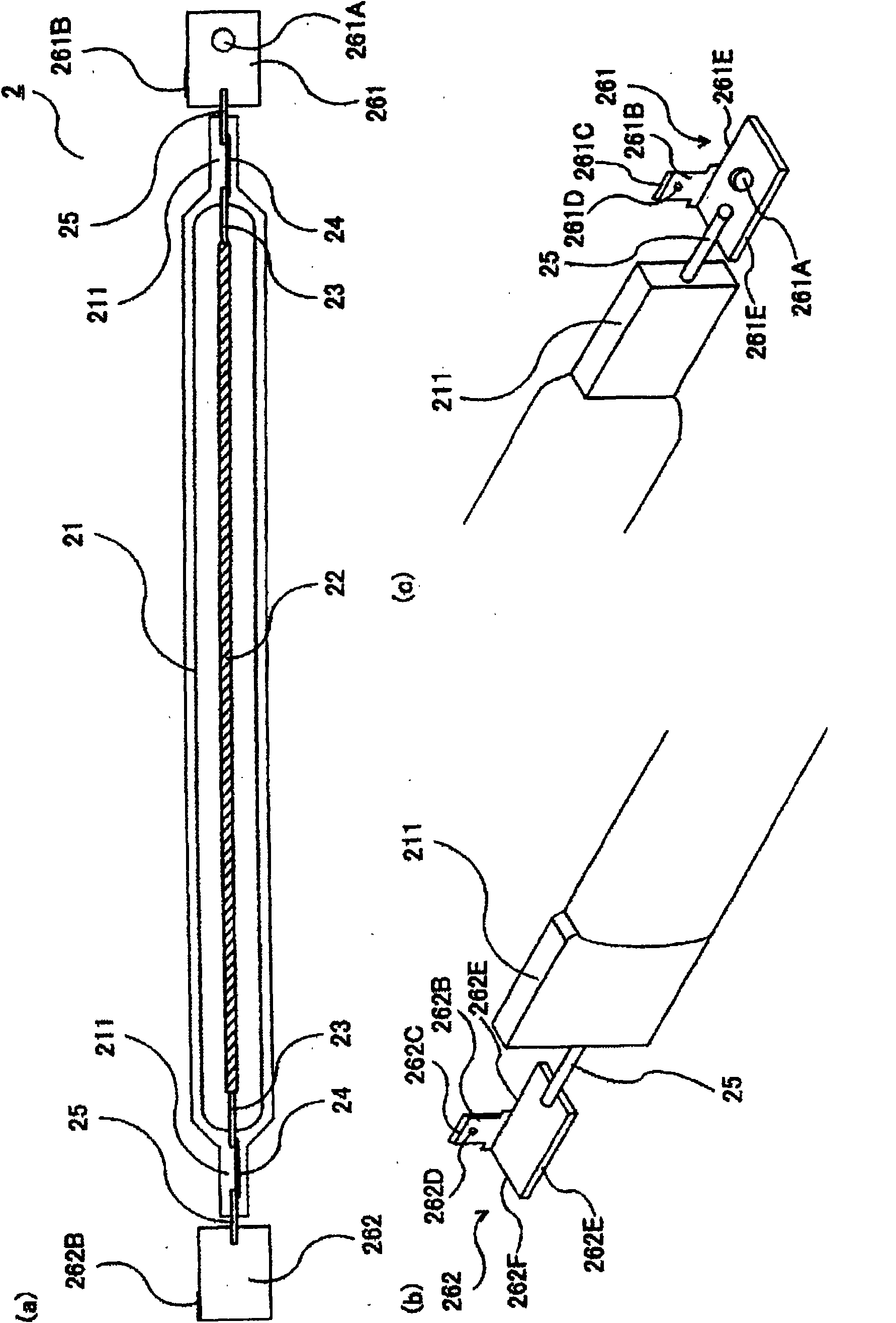
[0017] The heating device 1 receives the vibration caused by the rotational driving of the roller 3, but in the tubular incandescent lamp 2, the rod-shaped part of the fixing body 7 is inserted into the through-hole 261A of the one terminal 261, and the one terminal 261 is held by the one lamp holding part 61. , thereby restricting the movement of the tubular incandescent lamp 2 in the axial direction
Furthermore, the terminals 261, 262 at both ends of the tubular incandescent lamp 2 are clamped by the lamp holders 61, 62, thereby restricting the movement of the tubular incandescent lamp 2 in a direction perpendicular to the axial direction.

Method used


Image

  • Heating device
  • Heating device
  • Heating device

Examples


Embodiment Construction

[0057] The heating device of the present invention is characterized in that, in order to position the tubular incandescent lamp at a desired position, the screw is not directly fixed on the other terminal, and in order to restrict the direction of the other terminal to be perpendicular to the axial direction of the tubular incandescent lamp direction movement, the other terminal is arranged on the other lamp holding part, and the movement of the tubular incandescent lamp in the axial direction is restricted.

[0058] First, as a first embodiment of the heating device 1 of the present invention, refer to Figure 1 ~ Figure 3 The heating device 1 in which one terminal of a tubular incandescent lamp is fixed to a lamp holder will be described.

[0059] figure 1 It is an explanatory diagram of the heating device 1 according to the first embodiment, and is a cross-sectional view along the tube axis direction of the cylindrical roller 3 constituting the heating device 1 . figure...


PUM


Abstract

The invention aims to provide a heating device capable of positioning a tubular filament lamp in which screw nails as fixing bodies are reduced. The first invention relates to a heating device, comprising: a tubular filament lamp, having a bulb provided with a filament on the center shaft and a pair of terminals electrically connected with both ends of the filament; and a frame having lamp holding parts holding the terminals. The heating device is characterized in that the terminal at one end is fixed on the lamp holding part at the end in the manner that the movement in the axial direction and the movement in the direction orthogonal to the axial direction of the tubular filament lamp are limited, and the terminal at the other end is installed on the lamp holding at the other end in the manner that the movement in the direction orthogonal to the axial direction of the tubular filament lamp is limited and relative movement is carried out in axial direction relative to the other lamp holding part.

Description

technical field [0001] The present invention relates to a heating device used in toner fixing devices such as copiers and printers. Background technique [0002] Examples of the heating device used in the toner fixing device include those described in Patent Document 1 and Patent Document 2. [0003] refer to Figure 12 and Figure 13 A conventional heating device 1 will be described. [0004] Figure 12 It is an explanatory diagram of a conventional heating device 1 , and is a cross-sectional view along the tube axis direction of a cylindrical roller 3 constituting the heating device 1 . Figure 13 is constituted Figure 12 The explanatory diagram of the tubular incandescent lamp 2 of the heating device 1 shown is a cross-sectional view along the axial direction of the tubular incandescent lamp 2 . [0005] also, Figure 13 in, right and Figure 12 Like parts are shown with like reference numerals. [0006] A conventional heating device 1 has a cylindrical roller 3, an...

Claims


Application Information

Patent Timeline
Patent Type & Authority Patents(China)
IPC IPC(8): G03G15/20H01K1/46
CPCF21V19/00H01K1/22H01K3/12H01K7/00
Inventor 生岛和之寺尾勇哉
Owner USHIO DENKI KK
Learn More