Free ball bearing, support table, conveyance facility, and turntable

A technology of bearings and supporting balls, applied in rolling contact bearings, bearings, mechanical equipment, etc., can solve problems such as air pollution, main ball loss, particle scattering, etc., and achieve the effect of high degree of freedom in operation

Inactive Publication Date: 2012-04-18
GUCHI KIKO CO LTD
View PDF5 Cites 12 Cited by
  • Summary
  • Abstract
  • Description
  • Claims
  • Application Information

AI Technical Summary

Problems solved by technology

[0008] However, in the configuration using the rotation suppressing member that is in direct contact with the main ball, there is a problem that the main ball is worn out due to friction, and as a result, the generated particles are scattered into the transfer chamber su

Method used


Image

  • Free ball bearing, support table, conveyance facility, and turntable
  • Free ball bearing, support table, conveyance facility, and turntable
  • Free ball bearing, support table, conveyance facility, and turntable

Examples


no. 1 approach

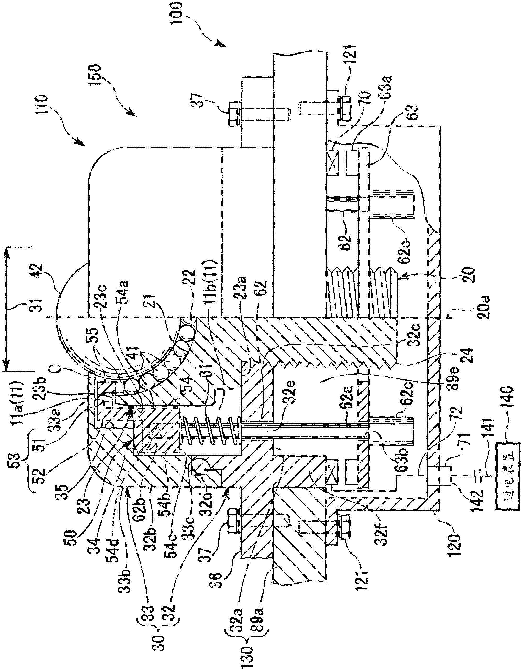
[0086] Below, refer to Figure 1~5 The first embodiment of the present invention (the bearing unit 100 , the free ball bearing 110 , and the support stand 89 of this embodiment) will be described.

[0087] Such as image 3 , Figure 4 , Figure 5 As shown, the bearing unit 100 described here includes a substrate positioning stage 89 (supporting stage) for precise positioning of a substrate 1 such as a display sample glass, a silicon substrate (wafer), etc. ). A free ball bearing 110 and a pressing drive device 70 (refer to figure 1 ), the cover part 120.

[0088] On platen 89a ( Figure 4 Among them, free ball bearings 110 protrude from a plurality of positions on the upper side of the platen 89a.

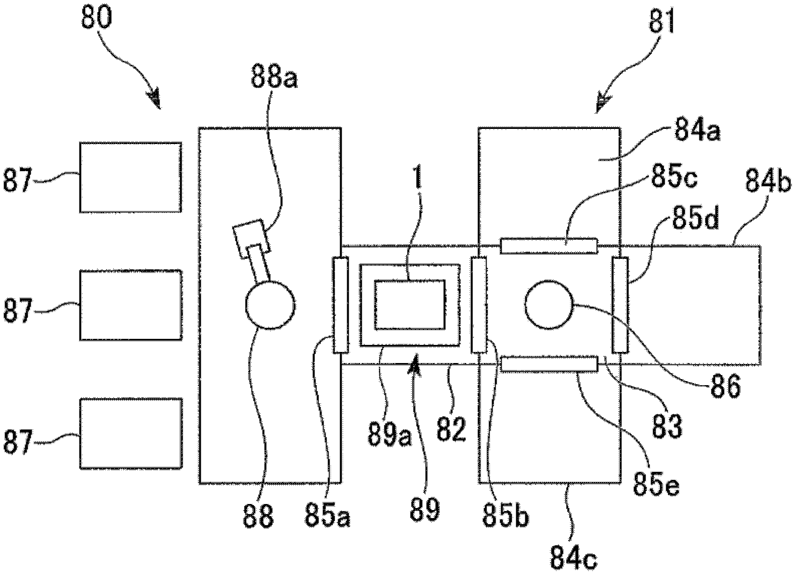
[0089] The above-mentioned positioning table 89 is set on the structure Figure 4 The vacuum device 81 of the process tool 80 is shown in a load lock chamber 82, a transfer chamber 83, a vacuum chamber (vacuum chamber) called a process chamber. In this embodiment, the case...

no. 2 approach

[0208] Next, refer to Figure 6 A second embodiment of the present invention will be described.

[0209] Such as Figure 6As shown, the bearing unit 300 of this embodiment employs an electric motor 370 (rotary driving means) as the driving means for pressing. In order to arrange this bearing unit 300 , bearing assembly parts 350 are provided at a plurality of places on the table plate 89 a of the positioning table 89 . In the bearing assembly body part 350, the free ball bearing 310, the said motor 370, and the cover member 120 are provided on the base plate 89a.

[0210] Instead of the supporting ball retaining ring 50, the case 30, and the driving force transmission rod 62 of the free ball bearing 110 described in the above-mentioned first embodiment, the free ball bearing 310 includes a supporting ball retaining ring 50A, a case 330, The driving force transmission shaft 371 .

[0211] The support ball snap ring 50A has a ring portion 354 with engaging teeth (base end si...

no. 3 approach

[0240] refer to Figure 7A , Figure 7B A third embodiment of the present invention will be described. The description of the points common to the first and second embodiments will be omitted, and the points of difference will be described in detail.

[0241] The free ball bearing 410 of this embodiment includes a support ball snap ring 450 , a reciprocating movable member 460 (movable body), and a driving force transmission shaft 471 as a driving device for pressing. The housing 430 of the free ball bearing 410 has internal threads on the inner side of the lower end thereof.

[0242] The base body 440 has a substantially disc-shaped top plate portion 440a, a substantially cylindrical side portion 440b, and a flange 440c extending radially outward from the lower end of the side portion 440b.

[0243] The base body 440 has external threads on the upper outer side of its side portion 440b. The inner thread of the housing 430 is screwed with the outer thread of the base 440 w...


PUM

PropertyMeasurementUnit
Surface resistivityaaaaaaaaaa
Volume resistivityaaaaaaaaaa

Abstract

A free ball bearing (110) comprises a support ball-pressing ring (50) disposed within a housing (30), and the support ball-pressing ring (50) is configured in such a manner that, in order to restrict or suppress the rolling of support balls (41,..., 41) arranged on a hemispherical recessed surface (21) or in order to release the restriction or suppression, the support ball-pressing ring (50) can move from a position (pressing position) at which the rolling of the support balls (41,..., 41) is restricted or suppressed, to a position (standby position) at which the restriction or suppression of the rolling of the support balls (41,..., 41) is released. The support ball-pressing ring (50) comprises a cylindrical pressing section (55) which, as the support ball-pressing ring (50) moves, can enter and exit the space between the hemispherical recessed surface (21) and a main ball (42) (said space being the space in which the support balls (41,..., 41) are arranged). When the support ball-pressing ring (50) is located at the pressing position, the pressing section (55) restricts or suppresses the rolling of the support balls (41,..., 41), and when the support ball-pressing ring (50) is located at the standby position, the restriction or suppression of the support balls (41,..., 41) is released.

Description

technical field [0001] The present invention relates to a free ball bearing, a support table using the free ball bearing, a transfer device, and a turntable. Background technique [0002] When a transfer table and a positioning table using free ball bearings are used, it is possible to move and rotate a conveyed object in any horizontal direction, and the frictional resistance against the conveyed object at this time is extremely small. Therefore, free ball bearings are used in manufacturing processes that require strict damage prevention or high positioning accuracy (for example, Patent Document 1). As this example, there is a substrate processing line (film formation, resist coating, exposure, etching, etc.), and specific conveyances include glass substrates such as FPD (flat panel display) sample glass for displays, semiconductor elements, and semiconductor Silicon substrates (wafers) for electronic components such as packages. [0003] In this processing, the processin...

Claims


Application Information

Patent Timeline
IPC IPC(8): B65G49/06B65G13/00B65G39/02B65G49/07F16C19/50F16C29/04H01L21/677
CPCF16C19/50F16C29/046B65G2249/02H01L21/6875B65G49/064B65G39/025H01L21/67201F16C29/04H01L21/67739H01L21/68714B65G2201/0297
Inventor 井口薰
Owner GUCHI KIKO CO LTD
Why Eureka
Try Eureka