Stator and rotor structure of built-in permanent magnet brushless direct current motor

A DC motor, stator rotor technology, applied in the direction of magnetic circuit shape/style/structure, magnetic circuit rotating parts, electrical components, etc., can solve large torque fluctuations and noise, inherent performance degradation of motors, and low utilization of permanent magnets and other problems, to achieve the effect of reducing vibration and noise, reducing the amount of copper used, and reducing the effect of magnetic flux leakage

Inactive Publication Date: 2014-10-15
SOUTHEAST UNIV
View PDF6 Cites 13 Cited by
  • Summary
  • Abstract
  • Description
  • Claims
  • Application Information

AI Technical Summary

Problems solved by technology

[0003] The working principle of the built-in "V" shaped permanent magnet brushless DC motor is that the rotating magnetic field generated by the electric excitation of the stator interacts with the magnetic field generated by the built-in permanent magnet in the rotor to make the rotor rotate; since the permanent magnet is embedded in the rotor, the rotor The surface is relatively smooth and has a salient pole effect, but it leads to a large leakage coefficient, a relatively small air gap flux, and a low utilization rate of the permanent magnet
Usually, magnetic isolation bridges and auxiliary slots are set on the rotor to reduce magnetic flux leakage; however, unreasonable settings of magnetic isolation bridges and auxiliary slots not only lead to a decline in the inherent performance of the motor, but may also cause greater torque fluctuations and noise; therefore, reasonable setting of permanent magnet position, magnetic isolation bridge and auxiliary slot has positive significance for improving motor efficiency and motor dynamic performance

Method used


Image

  • Stator and rotor structure of built-in permanent magnet brushless direct current motor
  • Stator and rotor structure of built-in permanent magnet brushless direct current motor
  • Stator and rotor structure of built-in permanent magnet brushless direct current motor

Examples


Embodiment Construction

[0027] The present invention will be further described below in conjunction with the accompanying drawings.

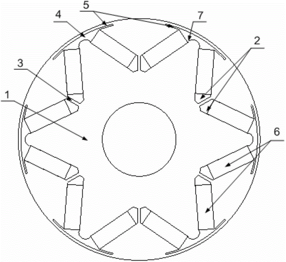
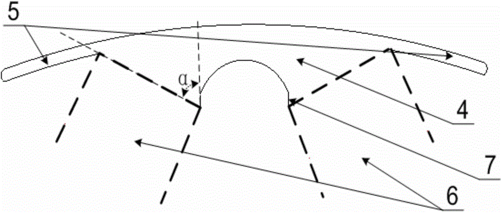
[0028] A stator-rotor structure of a built-in permanent magnet brushless DC motor, such as Figure 5 Shown: includes a stator and a rotor, the rotor is built into the stator, and the rotor is provided with more than one "V"-shaped groove (2) along the circumferential direction, and the opening of the "V"-shaped groove points to the stator; the The bottom of the other end of the "V"-shaped groove opposite to the opening is provided with a reinforcing rib (3). The opening ends of two adjacent "V"-shaped grooves are communicated through a connecting arched groove (4), and two symmetrical slot grooves ( 5); permanent magnets (6) with the same polarity are placed in the left and right grooves of each "V" shaped groove (2), and the magnetization direction of the permanent magnets (6) is perpendicular to the permanent magnet surface, while the adjacent " The polarities of t...


PUM


Abstract

The invention discloses a stator and rotor structure of a built-in permanent magnet brushless direct current motor, and belongs to the technical field of motors. The stator and rotor structure of the built-in permanent magnet brushless direct current motor is characterized in that more than one V-shaped groove (2) is formed in the circumference of a rotor, opening ends of each two adjacent V-shaped grooves are communicated through a communication arch groove (4), two symmetrical gap grooves (5) are located in the direction towards the interior of the opening end of each V-shaped groove, permanent magnets (6) of the same polarity are placed in the left portion and the right portion of each V-shaped groove (2), the polarities of the permanent magnets in each two adjacent V-shaped grooves are opposite, an inclined bevel (7) is arranged at the bottom of each communication arch groove (4), and the external circle of a stator (8) is processed by using an enneagon irregularity edge cutting method, and is of three phase fraction slot centralization winding structure. The stator and rotor structure of the built-in permanent magnet brushless direct current motor not only can improve efficiency of the built-in V-shaped permanent magnet brushless direct current motor, but also can reduce output torque fluctuation, and has the advantages of reducing magnetic leakage flux during the same period, and being low in noise and high in efficiency.

Description

technical field [0001] The invention relates to a high-efficiency built-in permanent magnet type brushless DC motor stator and rotor structure, which belongs to the technical field of motors. Background technique [0002] Energy shortage is a common concern of the whole world, and energy saving is the theme of the development of the world today; at present, industrial motors consume 30%-40% of the world's power generation, so improving the efficiency of industrial motors can achieve obvious energy-saving effects. Since the permanent magnet brushless DC motor adopts permanent magnet excitation and has no rotor resistance loss during stable operation, it can reduce the fan (small-capacity motor can even remove the fan) and the corresponding wind friction due to the reduction of total loss, so it has great advantages. Large efficiency improvement space and advantages. According to the characteristics of the permanent magnet brushless DC motor, the efficiency of the permanent m...

Claims


Application Information

Patent Timeline
Patent Type & Authority Applications(China)
IPC IPC(8): H02K1/27H02K1/16H02K29/03
Inventor 林明耀徐磊李红艳
Owner SOUTHEAST UNIV
Why Eureka
Try Eureka