T type two spout hand riveter

A riveting gun and handle-type technology, which is applied in the direction of hand-held tools and manufacturing tools, can solve the problems of inconvenient packaging, transportation and carrying, increased production costs, laborious use, etc., and achieve the effect of solving the problem of functional limitations

Inactive Publication Date: 2009-12-16
袁建明
View PDF2 Cites 5 Cited by
  • Summary
  • Abstract
  • Description
  • Claims
  • Application Information

AI Technical Summary

Problems solved by technology

[0004] However, the defect in the prior art is that the pulling force direction of the pull rod and the moving direction of the rivet are perpendicular to each other when pulled, and the forces are all on the same plane.
According to the principle of leverage, the farther the distance between the two screws is, the longer the length of the handle as the force arm is bound to be, otherwise it will be very laborious to use
The lengthening of the handle will inevitably increase the volume of the riveting gun, resulting in an increase in production costs, and it is not easy to pack, transport and carry

Method used


Image

  • T type two spout hand riveter
  • T type two spout hand riveter
  • T type two spout hand riveter

Examples


Embodiment 1

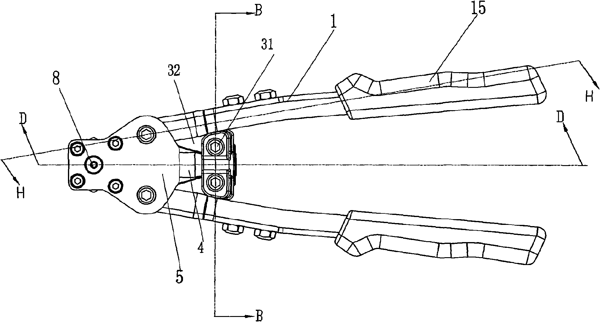
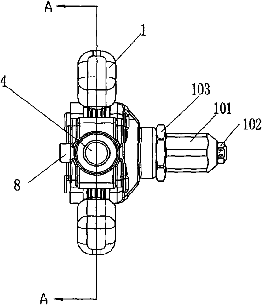
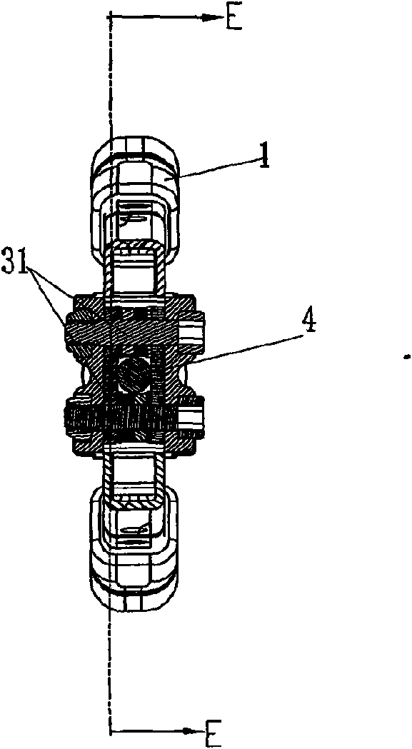
[0042] Such as Figure 1 to Figure 8 Shown, a kind of T-shaped double handle type riveting gun, comprises riveting gun seat 12 ( Figure 5 ), the left and right handles 1 hinged with the riveter base 12 on the left and right sides of the riveter base, the horizontal pull rod 4 that is movably inserted in the riveter base 12, and the horizontal pull rod 4 is arranged between the left and right handles 1 The horizontal tie rod stretching mechanism 3, the adjustment mechanism 10 and the blind rivet grasping mechanism 11 provided inside the adjustment mechanism 10; it is characterized in that: a vertical pull rod 8 pulled by the horizontal pull rod 4 is also provided in the rivet gun seat 12 The lower end of the rivet gun seat 12 at one end of the vertical pull rod 8 is provided with the adjustment mechanism 10, and the inside of the adjustment mechanism 10 is provided with a rivet gripping mechanism 11 at the head of the vertical pull rod 8; The connection between the vertical p...

Embodiment 2

[0055] The structure of embodiment 2 is basically the same as that of embodiment 1, the only difference between the two is that the fixing groove 41 provided at the tail end of the transverse tie rod 4 is an annular groove (the figure of embodiment 2 is omitted). The tail end of the transverse tie rod is provided with a circular fixing groove whose diameter is less than its cross-sectional diameter for easy processing, but it is also very convenient and firm to be connected with the transverse connecting rod 4 after the fixing plate 35 is installed. Embodiment 2 has all the advantages of Embodiment 1.

[0056] Figure 9 , 10 It is the other two structures of the "L" type connecting rod. Figure 9 The "L" type connecting rod is provided with "L" type connecting rod central hole 72, connecting hole 73, also is provided with an oval hole in the other end 71 places of " L " type connecting rod. When using this "L" type connecting rod, the connecting portion of the "L" type conn...

Embodiment 3

[0059] The product structure of embodiment 3 is close to embodiment 1 and 2. Such as Figure 11-15 as shown, Figure 11 and figure 1 similar Figure 12 , 13 , 14, 15 and Figure 5 , 6 , 7, and 8 are similar, or even the same. In Embodiment 3, the components of the vertical pull-rod pulling mechanism 6 , the transverse pull-rod stretching mechanism 3 and the adjustment mechanism 10 have the same connection relationship. The difference between Embodiment 3 and Embodiments 1 and 2 is that in the adjustment mechanism 10 of Embodiment 3, a blind rivet nut gripping mechanism 11' is installed on the head of the vertical pull rod 8 to replace the pulling mechanism 11' of Embodiment 1. Rivet gripping mechanism 11. The blind rivet nut grasping mechanism 11' is mainly composed of a blind rivet screw 111'. The rear end of the vertical pull rod 8 is provided with a knob 17 capable of rotating the vertical pull rod. In order to facilitate the rotation of the knob 17 to rotate the ...


PUM


Abstract

The invention discloses a T type two spout hand riveter. The riveter comprises a riveter seat, left and right handles which are positioned on both sides of the riveter seat and are hinged with the riveter seat, a lateral pull rod which is movably inserted in the riveter seat, a lateral pull rod stretching mechanism arranged between the lateral pull rod and the left and right handles, a regulating mechanism, and a blind rivet grasping mechanism in the regulating mechanism. The T type two spout hand riveter is characterized in that the inside of the riveter seat is also provided with a vertical pull rod, the lower end of the riveter seat at one end of the vertical pull rod is provided with the regulating mechanism, and the head of the vertical pull rod is provided with the blind rivet grasping mechanism; and a connecting part of the vertical pull rod and the lateral pull rod is provided with a vertical pull rod pulling mechanism which mainly comprises an L type connecting rod. The invention is the hand riveter, and is a rivet setting piler if a blind rivet nut grasping mechanism is used for substituting the blind rivet grasping mechanism. The action of the vertical pull rod pulling mechanism ensures that the lateral pulling force of the lateral pull rod is converted into vertical pulling force, which mainly solves the problem of the limitation of use function of the prior hand riveters.

Description

technical field [0001] The invention relates to a riveting gun, in particular to a double handle riveting gun. Background technique [0002] Rivet guns can be divided into rivet guns and rivet nut guns. Generally speaking, the rivet gun uses the core pulling rivet for riveting; the rivet nut gun uses the rivet nut for riveting. [0003] However, the above-mentioned riveting parts must be riveted with a special tool - riveting gun. At present, riveting guns are divided into manual riveting guns, electric riveting guns and pneumatic riveting guns. Among them, manual riveting guns are very popular because of their low requirements for use. The use of double-handled riveting guns in manual riveting guns is particularly widespread. Manual rivet guns usually include a rivet gun seat, two handles arranged on both sides of the rivet gun seat, an adjustment mechanism arranged at the front end of the rivet gun seat, and a rivet gripping mechanism or a rivet nut installed in the ad...

Claims


Application Information

Patent Timeline
Patent Type & Authority Applications(China)
IPC IPC(8): B21J15/38
CPCB21J15/386B21J15/043B25B27/0007
Inventor 袁建明
Owner 袁建明
Why Eureka
Try Eureka