Remote monitoring and controlling type optical receiver

An optical receiver and remote monitoring technology, which is applied in the direction of TV system adapting to optical transmission, adapting to cable transmission, etc., can solve the problems of high network operation cost, troublesome debugging, and low work efficiency, and achieve the reduction of network operation cost and dispatch The number of times of work, the effect of improving work efficiency

Active Publication Date: 2009-12-23
陕西迈克高新科技实业集团有限公司
View PDF0 Cites 7 Cited by
  • Summary
  • Abstract
  • Description
  • Claims
  • Application Information

AI Technical Summary

Problems solved by technology

[0004] The present invention provides a remote monitoring and control type optical receiver to overcome the problems of large amount of debugging and maintenance, troublesome debugging, low work efficiency and high network operation cost existing in the prior art

Method used


Image

  • Remote monitoring and controlling type optical receiver
  • Remote monitoring and controlling type optical receiver

Examples


Embodiment Construction

[0015] The present invention will be described in detail below in conjunction with the accompanying drawings.

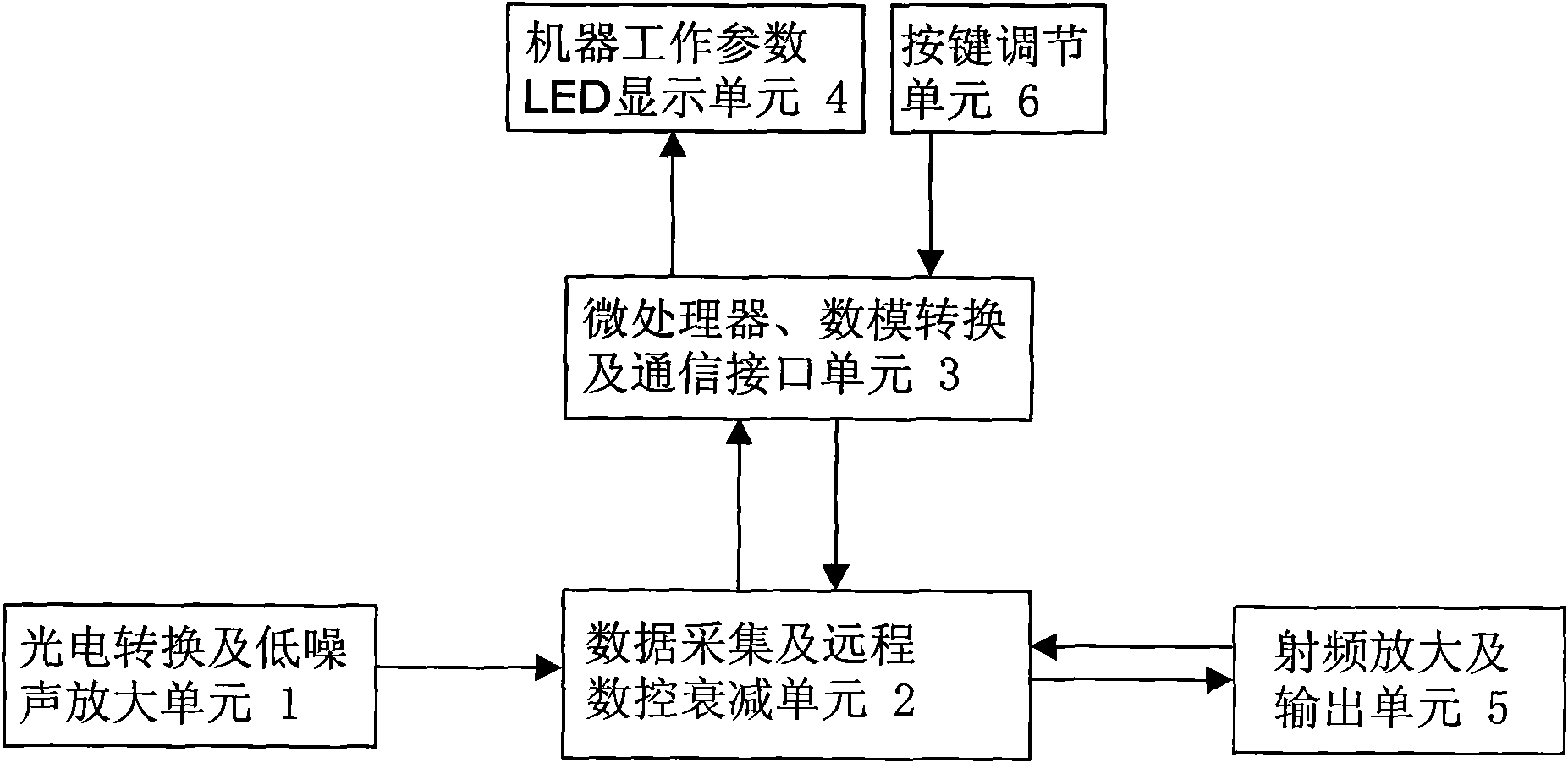
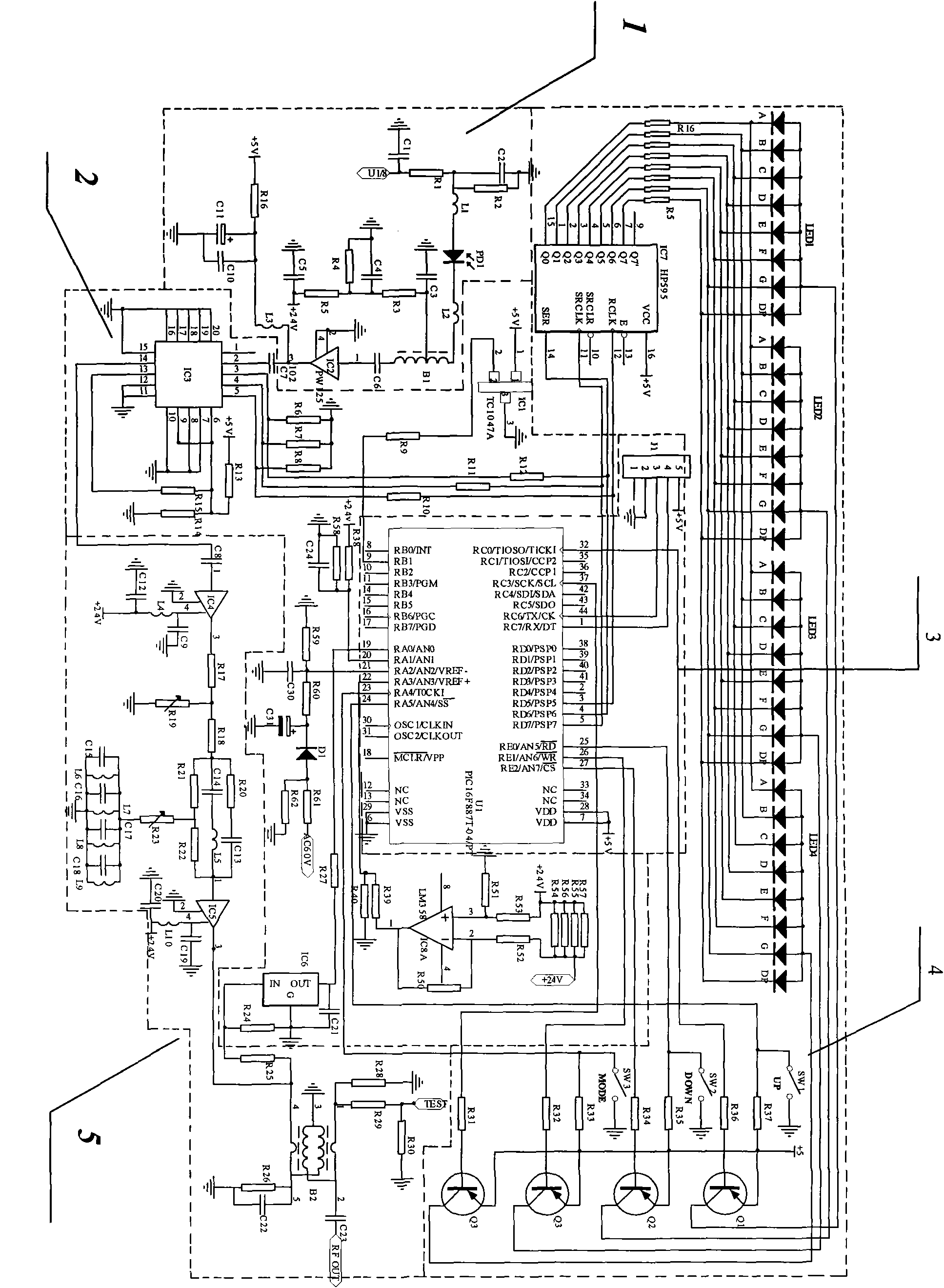
[0016] see figure 1 , a remote monitoring and control type optical receiver, including photoelectric conversion and low noise amplification unit 1, data acquisition and remote numerical control attenuation unit 2, radio frequency amplification and output unit 5, microprocessor, analog-to-digital conversion and communication interface unit 3. Machine working parameter LED display unit 4 and button adjustment unit 6; said photoelectric conversion and low noise amplification unit 1 are respectively connected to data acquisition and remote numerical control attenuation unit 2 and microprocessor, analog-to-digital conversion and communication interface unit 3; The data acquisition and remote numerical control attenuation unit 2 is respectively connected with the microprocessor, the analog-to-digital conversion and communication interface unit 3 and the radio frequency amp...


PUM


Abstract

The invention relates to the technical field of broadband multimedia access networks, in particular to a remote monitoring and controlling type optical receiver. The invention aims to solve the problems of large debugging and maintaining amount, troublesome debugging, low working efficiency and high network running cost in the prior art. The remote monitoring and controlling type optical receiver comprises a photoelectric conversion and low noise amplification unit, a radio frequency amplification and output unit, a data acquisition and remote numerical control attenuation unit, a microprocessor, an analog-to-digital conversion and communication interface unit, a machine working parameter LED display unit and a button adjusting unit. Compared with the prior art, the invention has remote control, reduces the working amount of site debugging and maintaining, improves the working efficiency and greatly reduces the network operation cost.

Description

Technical field: [0001] The invention relates to the technical field of broadband multimedia access network, in particular to a remote monitoring and control type optical receiver. Background technique: [0002] With the transformation of the HFC network from a simple cable TV broadcast network to a broadband multimedia access network, its business volume has increased sharply, and the number of optical receivers and the amount of debugging have also increased, and the link loss of each optical receiver is different. The difference in optical receiving power leads to uneven output RF levels of each optical receiver in the system, while traditional optical receivers require engineering debuggers to go to the site to rely on test instruments to debug, maintain and troubleshoot one by one, which also makes the optical receiver The debugging and maintenance work of the project has become particularly cumbersome. How can the engineering personnel not be on site so that the optica...

Claims


Application Information

Patent Timeline
IPC IPC(8): H04N7/22
Inventor 陈苏南王晓建
Owner 陕西迈克高新科技实业集团有限公司
Why Eureka
Try Eureka