Image filling method, device and equipment

A filling method and filling device technology, applied in the video field, can solve the problems of multiple coding bits, occupation, and no consideration of motion information, etc., and achieve the effect of improving efficiency and reducing the number of coding bits.

Active Publication Date: 2013-06-12
MIGU CO LTD
View PDF0 Cites 0 Cited by
  • Summary
  • Abstract
  • Description
  • Claims
  • Application Information

AI Technical Summary

Problems solved by technology

[0008] 1. Since the direct copy filling method or the mirror copy filling method only considers the continuity of the texture information in the vertical direction of the image, no matter whether inter prediction or intra prediction coding is used, the filling area will inevitably have a non-zero prediction difference value exists, and a non-zero prediction difference will take up more encoding bits
[0009] 2. When a series of changes in the position of the camera, such as translation, rotation around the object, shaking (such as fore, etc., will cause the object at the right and bottom sides of the image to go out and in, the existing filling method will determine the image The process of filling the value does not take these motion information into account, which will inevitably lead to low efficiency of the filling area as inter prediction or intra prediction

Method used


Image

  • Image filling method, device and equipment
  • Image filling method, device and equipment
  • Image filling method, device and equipment

Examples


Embodiment 1

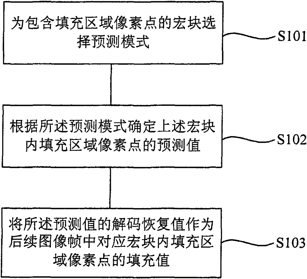
[0025] Such as figure 1 Shown is a schematic flow chart of an image filling method provided by Embodiment 1 of the present invention. It should be noted that the description of this embodiment is described from the encoding end of image coding, and the method includes the following steps: S101: To include filling Select the prediction mode for macroblocks of area pixels.

[0026] In the embodiment of the present invention, a prediction mode may be selected for prediction for a macroblock including pixels in the padding area, so as to improve the efficiency of the above-mentioned macroblock predictive coding.

[0027] There are two basic prediction modes in image coding: inter-frame prediction mode and intra-frame prediction mode. The inter-frame prediction mode uses the correlation between image frames, that is, temporal correlation, to achieve the purpose of image compression. Moving images are A temporal image sequence composed of consecutive image frames at intervals of fr...

Embodiment 2

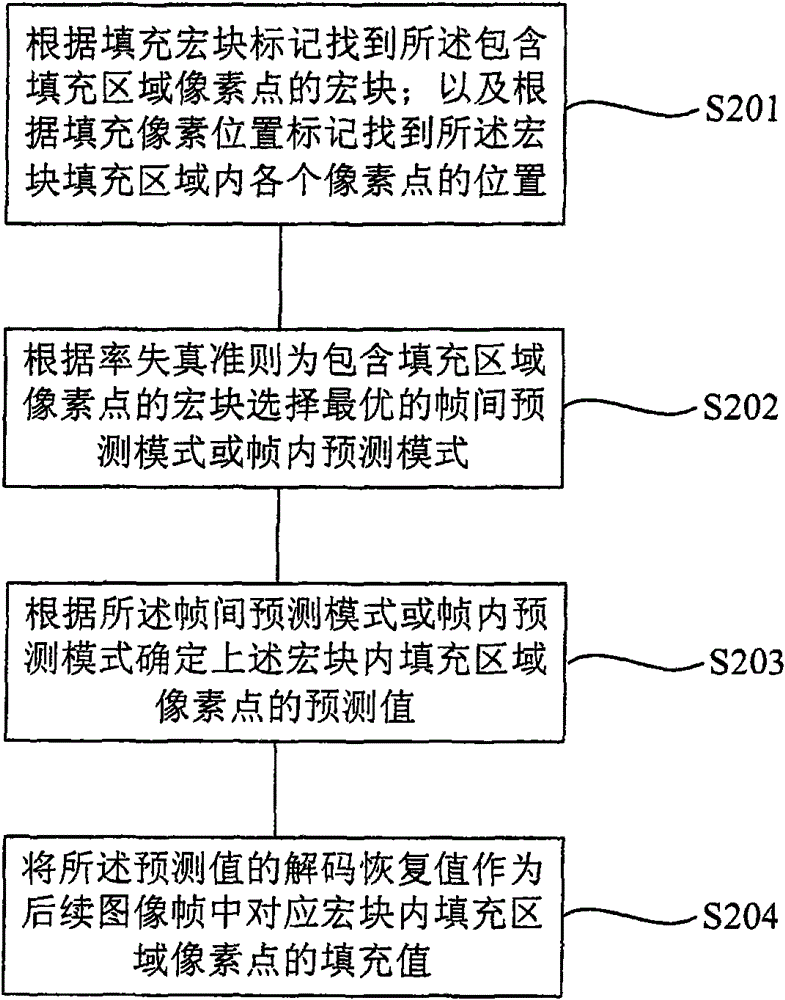
[0049] Such as figure 2 Shown is a schematic flowchart of an image filling method provided by Embodiment 2 of the present invention, and the method includes the following steps:

[0050] S201: Find the macroblock containing the pixels in the filled area according to the filled macroblock mark; and find the position of each pixel in the filled area of ​​the macroblock according to the filled pixel position mark. The image filling method in the embodiment of the present invention operates in units of macroblocks, therefore, it is necessary to accurately locate the macroblock to be filled and the position of the pixel to be filled in the macroblock.

[0051] In the embodiment of the present invention, the macroblock containing the pixels in the padding area is found by using the padding macroblock mark. The padding macroblock mark records "whether the pixel in the padding area is contained in the current macroblock"; and the padding pixel position records " The position identif...

Embodiment 3

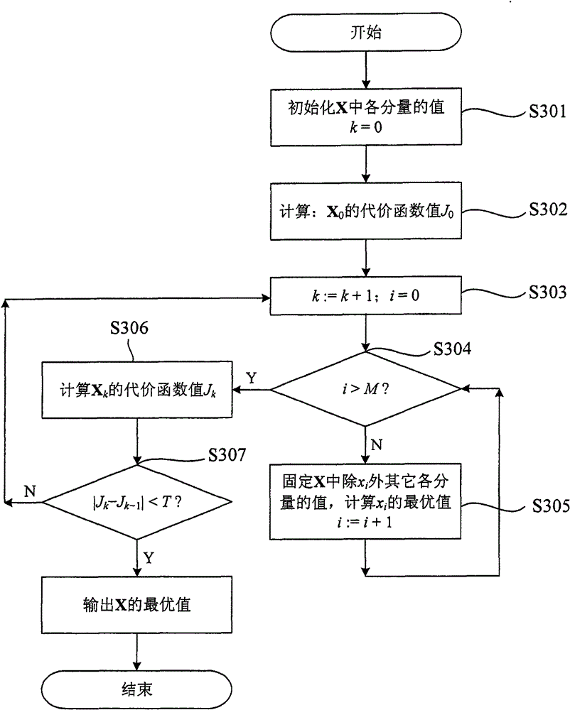
[0066] Such as image 3 Shown is a flow chart of a method for calculating the optimal value of pixels in a filling area provided by Embodiment 3 of the present invention. This embodiment is a detailed description of step S202 and step S203 in the second embodiment.

[0067] Such as image 3 As shown, this method for calculating the optimal value of pixels in the filled area includes the following steps:

[0068] S301: Initialize X k The value of each component in, X is the value of the pixel point of the padding area in the macroblock, X=(x 0 , x 1 ,...,x N-1 ) T , M is the number of pixels in the filling area, and at this time, the number k of the inter-frame prediction mode or the intra-frame prediction mode=0.

[0069] The value of each component in X in this step can be determined by using the "direct copy filling method" or "mirror copy filling method" in the prior art.

[0070] S302: Calculate X by the following formula 0 The cost function value J 0 :

[0071]...


PUM


Abstract

The embodiment of the invention provides an image filling method, a device and equipment. The method includes the steps of: selecting a prediction model for an image block comprising a filling region pixel point; according to the prediction model, determining the prediction value of the filling region pixel point in the image block; and using a decoding restore value of the predication value as afilling value of the filling region pixel point in a corresponding image block of a subsequent image frame. The embodiment uses the decoding restore value as the filling value of the filling region pixel point in the corresponding image block of the subsequent image frame, thus leading the prediction differences of the pixel points in the filling region to be zero and consequently decreasing the coding bit numbers occupied by the filling region. In addition, the embodiment also applies the prediction model for the filling region and fully utilizes the interframe or intra-frame correlation of the filling region, thus improving the interframe or intra-frame predication efficiency.

Description

technical field [0001] The present invention relates to the field of video technology, in particular to an image filling method, device and equipment. Background technique [0002] Most of the existing video coding standards are designed based on an image size of Mx(NxN), where NxN is the size of a macroblock (both M and N are integer values). Currently, the latest video coding standard H.264 Video Coding Standard / Advanced Video Coding Standard (H.264 / AVC) uses NxN (the value of N is 16) macroblock as its basic syntax and semantics unit. [0003] The image filling technology is to realize arbitrary resolution video encoding. The so-called arbitrary resolution video encoding means that the width and height of the rectangular image in the input video sequence can be any value, that is, the image size may not be an integer multiple of the above-mentioned macroblock. Because when the image size is not an integer multiple of the macroblock, the image encoder needs to fill a cert...

Claims


Application Information

Patent Timeline
Patent Type & Authority Patents(China)
IPC IPC(8): H04N7/26H04N7/50H04N19/567H04N19/593
Inventor 林四新李明常义林
Owner MIGU CO LTD
Why Eureka
Try Eureka