
Construction machinery

A technology for construction machinery and racks, which is used in motor vehicles, mechanically driven excavators/dredgers, earth movers/shovels, etc., can solve the problem of not fully ensuring the support of the center rack, side racks and the cab Beam joint length, local stress concentration, joint strength reduction and other problems, to achieve the effect of improving rigidity, increasing strength, and reducing noise

Active Publication Date: 2013-04-03
NIHON KENKI CO LTD
View PDF3 Cites 0 Cited by
  • Summary
  • Abstract
  • Description
  • Claims
  • Application Information

AI Technical Summary

Problems solved by technology

[0012] As a result, the joint length between the center frame and side frames and the cab support beam cannot be sufficiently ensured
Therefore, when a torsional force acts on the revolving frame due to the load of the counterweight, local stress concentration tends to occur at the junction of the center frame, the side frames, and the cab support beam, and there is a joint strength of the cab support beam against the torsional force. problems such as lowering

Method used


Image

  • Construction machinery
  • Construction machinery
  • Construction machinery

Examples


Embodiment Construction

[0034] Hereinafter, an embodiment of the construction machine according to the present invention will be described in detail with reference to the drawings, taking the case of applying it to a compact excavator as an example.

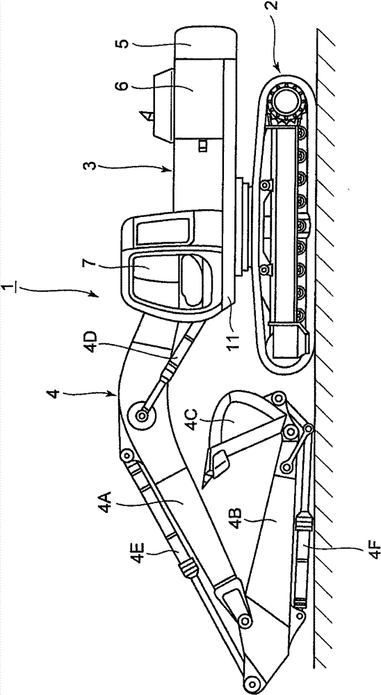
[0035] first, Figure 1 to Figure 5 The first embodiment of the present invention is shown, and in the drawings, reference numeral 1 denotes a hydraulic excavator as a representative example of a construction machine. Moreover, the vehicle body of the hydraulic excavator 1 generally includes: a crawler-type undercarriage 2 capable of self-propelling, and an upper revolving unit 3 mounted on the undercarriage 2 so as to be able to turn, and on the front side of the upper revolving unit 3 , the working device 4 for excavating soil, sand, etc. is provided in a vertically movable manner.

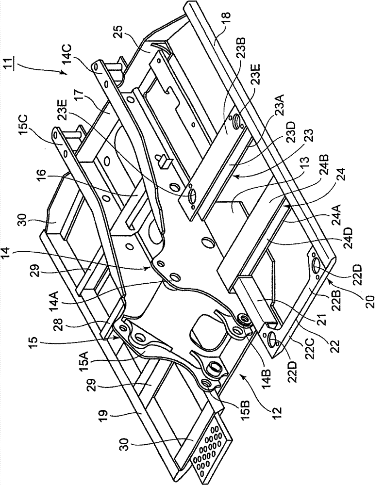
[0036] Here, the upper revolving body 3 generally includes: a revolving frame 11 described later as a vehicle body frame; The front side of the counterweight 5 accommod...


PUM


Abstract

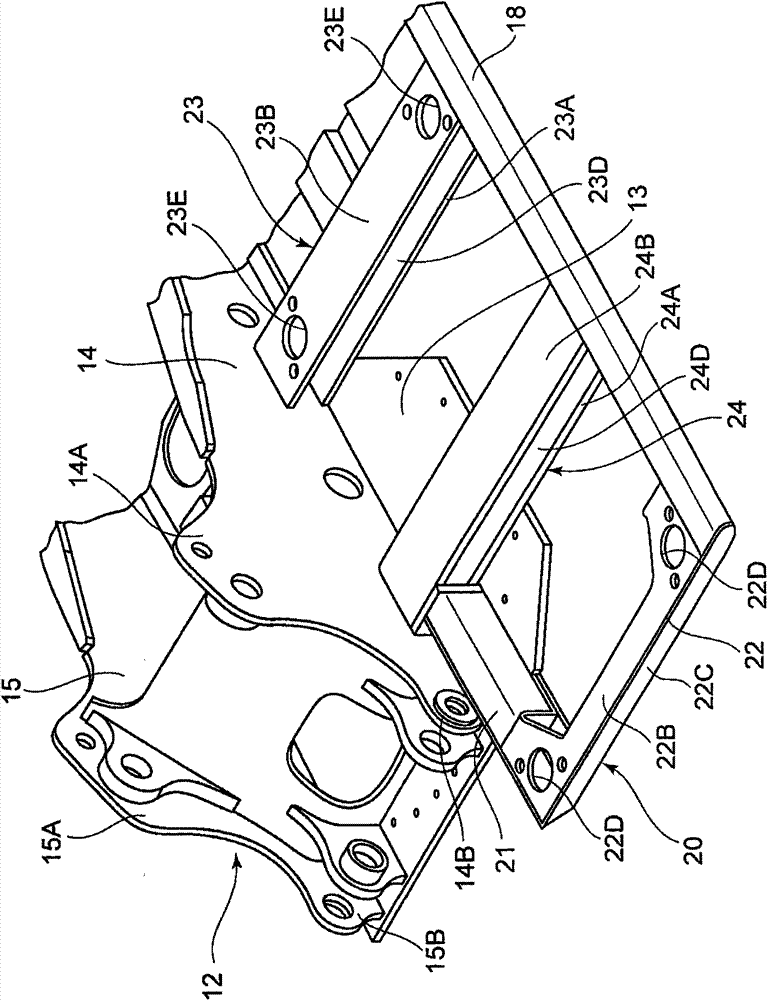
The objective of construction machinery of the invention is to reduce noise transmitted to a driving cab and to improve bond strength of a beam to a central framework and a lateral framework. A driving cab support beam (23) which supports the driving cab (7) is formed by using a lower beam (23A), an upper beam (23B), a back longitudinal beam (23C) and an opening (23D) in form of transverse U shaped cross section with an opening in front side. Therefore, seal space is not formed in the driving cab support beam, which is able to prohibit the noise generated by engine etc. from being enhanced due to resonance in the driving cab support beam. In addition, the opening (23D) of the driving cab support beam (23) is configured by way of facing the opening in front side of the driving cab support frame (20), which is able to enhance the bond strength of rear side of the driving cab support beam (23) adjacent to a counterweight (5) and to enhance the bond strength of the driving cab support beam (23) to a left longitudinal plate (14) and a left framework (18) of the central framework (12).

Description

technical field [0001] The present invention relates to construction machines such as hydraulic excavators, and more particularly to construction machines provided with a cab on a vehicle body frame. Background technique [0002] In general, a hydraulic excavator as a construction machine roughly includes: a self-propelled undercarriage; an upper revolving body rotatably mounted on the undercarriage; and a working device provided on the front side of the upper revolving body. . In addition, the upper revolving body has a vehicle body frame (revolving frame) serving as a base, and a working device capable of pitching is provided on the front side of the revolving frame, and an extractor is provided on the rear side of the revolving frame. A counterweight that balances the weight of the work equipment. In addition, a cab that defines an operator's cab is provided on the left side of the front part of the revolving frame, and a house cover for storing a prime mover and the li...

Claims


Application Information

Patent Timeline
Patent Type & Authority Patents(China)
IPC IPC(8): E02F3/04E02F9/00E02F9/16
CPCB60Y2200/412B62D21/186E02F3/36E02F9/0808E02F9/166
Inventor 小林敬弘平松秀文
Owner NIHON KENKI CO LTD
Learn More