Engine generator

An engine-driven and generator technology, applied in the direction of machines/engines, mechanical equipment, etc., can solve the problems of increasing the transport capacity of engine-driven generators, and the inability of engine-driven generators to adapt to various transportation methods, etc., to achieve the goal of transporting engine-driven The effect of easy-to-size generator and easy transportation

Active Publication Date: 2009-12-30
HONDA MOTOR CO LTD
View PDF1 Cites 11 Cited by
  • Summary
  • Abstract
  • Description
  • Claims
  • Application Information

AI Technical Summary

Problems solved by technology

Therefore, the above-mentioned engine-generator cannot be adapted to various transportation methods, and it is necessary to increase the transportation capacity of this type of engine-generator

Method used


Image

  • Engine generator
  • Engine generator
  • Engine generator

Examples


Embodiment Construction

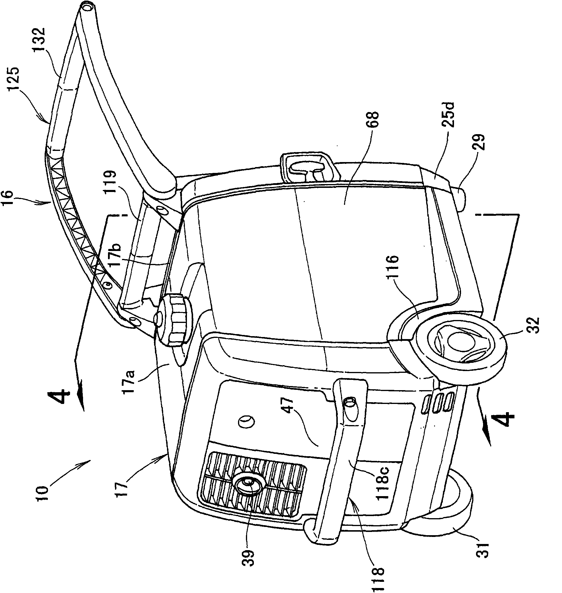
[0039] The term "forward" used herein refers to a direction in which the engine generator 10 according to the present invention is pulled by the pull handle 125 .

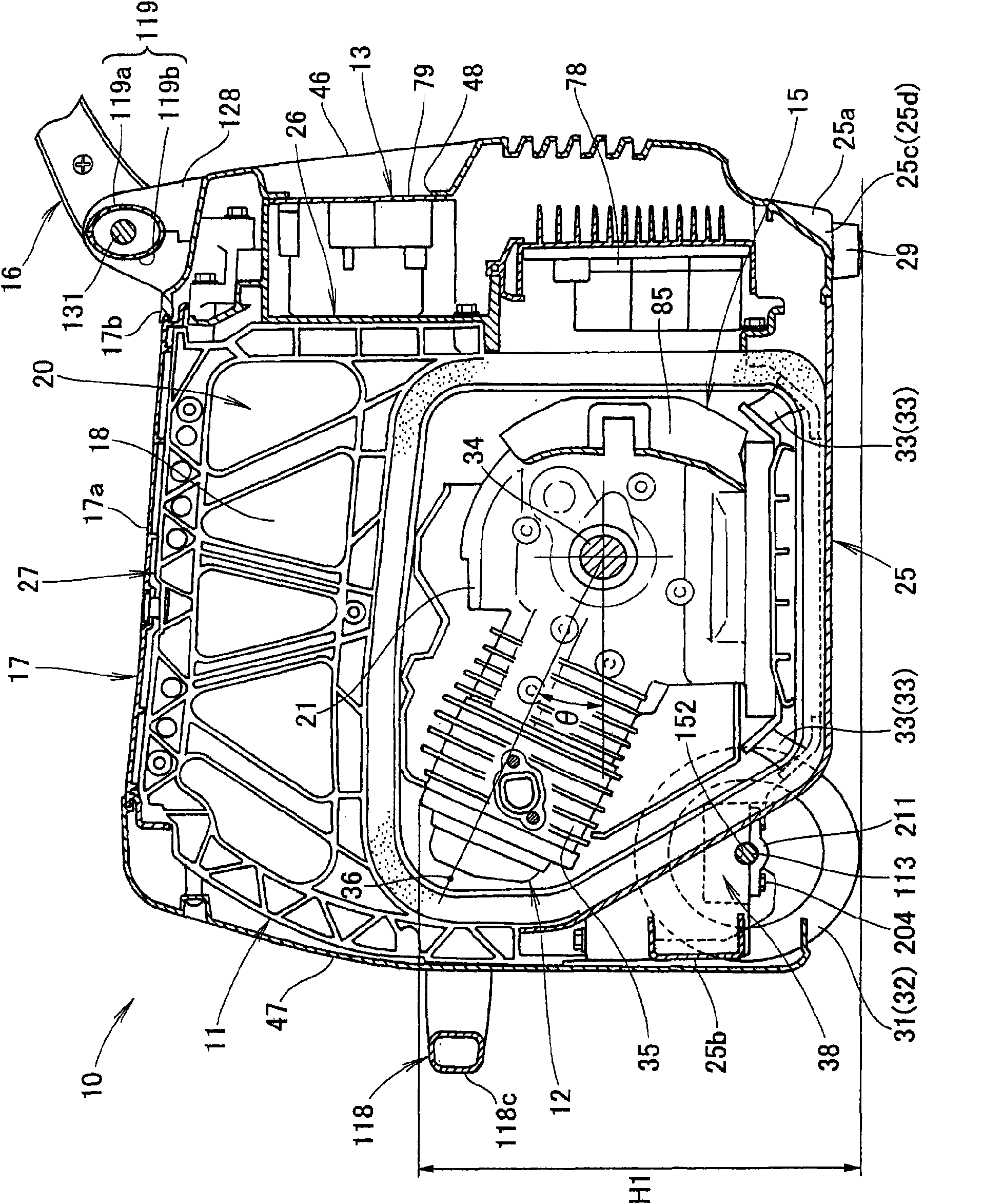
[0040] exist figure 1 and 2Among them, the engine generator 10 includes: a frame member 11 forming a frame body; an engine / generator unit 12 provided on the frame member 11; and an electronic component part 13 for controlling the output of the engine / generator unit 12; Inlet / fuel supply mechanism 14 for supplying fuel to engine / generator unit 12 (see Figure 4 ); a cooling structure 15 for guiding the cooling air to the engine / generator unit 12; a transport structure 16 for transporting the engine / generator unit 10; a housing for covering the engine / generator unit 12 and the electronic component part 13 17; the insulating material 18 used to separate the accommodating space 20 in the housing 17; and the muffler 23 (see Figure 4 ).

[0041] The engine generator 10 has left and right leg portions 29 provided on ...


PUM


Abstract

The invention relates to an engine generator accommodating an engine (21) and a generator (22) inside a case (17). A first stationary handle (118) that extends in the width direction is mounted in the rear section of the case. A second stationary handle (119) is mounted on the upper front part of the case. A draw handle (125) is provided so as to swing in the vertical direction in relation to the second stationary handle. The second stationary handle is manually grasped and the engine generator is moved. The first and second stationary handles are grasped and the engine generator is lifted. The draw handle is pulled to move the engine generator.

Description

technical field [0001] The present invention relates to a wheeled engine-driven generator, wherein the engine and the generator are accommodated in a casing. Background technique [0002] The engine-driven generator known in the prior art is provided with wheels and feet on the bottom cover, the engine and the generator are contained in a housing, and the handle for transportation is arranged on the upper side of the housing and on the opposite side of the wheels , such as the engine generator disclosed in Japanese Patent Application Laid-Open Publication No. 2005-76550 by way of example. [0003] The transport handles for transporting the engine-driven generator extend approximately horizontally from the left and right ends of the casing in the direction in which the handle rods depart from the casing, and the handles are arranged on the far ends of the left and right handle rods. [0004] According to the engine generator, pushing the transport handle while grasping and r...

Claims


Application Information

Patent Timeline
Patent Type & Authority Applications(China)
IPC IPC(8): F02B63/04
Inventor 平沼淳二进正则结城仁柴田良辅
Owner HONDA MOTOR CO LTD
Why Eureka
Try Eureka