Unlock instant, AI-driven research and patent intelligence for your innovation.

Guide vane duct element for a guide vane assembly of a gas turbine engine

一种燃气涡轮机、管道元件的技术,应用在发动机元件、发动机的冷却、发动机功能等方向,能够解决制造精度高、大热阻抗、降低冷却效率等问题,达到快速检测和更换、提高热力有效点火温度、改进输出和效率的效果

Inactive Publication Date: 2010-01-06
SIEMENS AG
View PDF0 Cites 13 Cited by
  • Summary
  • Abstract
  • Description
  • Claims
  • Application Information

AI Technical Summary

Problems solved by technology

This results in a greater thermal impedance which again reduces cooling efficiency
[0012] The object of the present invention is to provide an inlet guide vane arrangement for a gas turbine engine in which the guide vane duct elements have a high cooling efficiency but still have a high manufacturing accuracy

Method used


Image

  • Guide vane duct element for a guide vane assembly of a gas turbine engine
  • Guide vane duct element for a guide vane assembly of a gas turbine engine
  • Guide vane duct element for a guide vane assembly of a gas turbine engine

Examples


Embodiment Construction

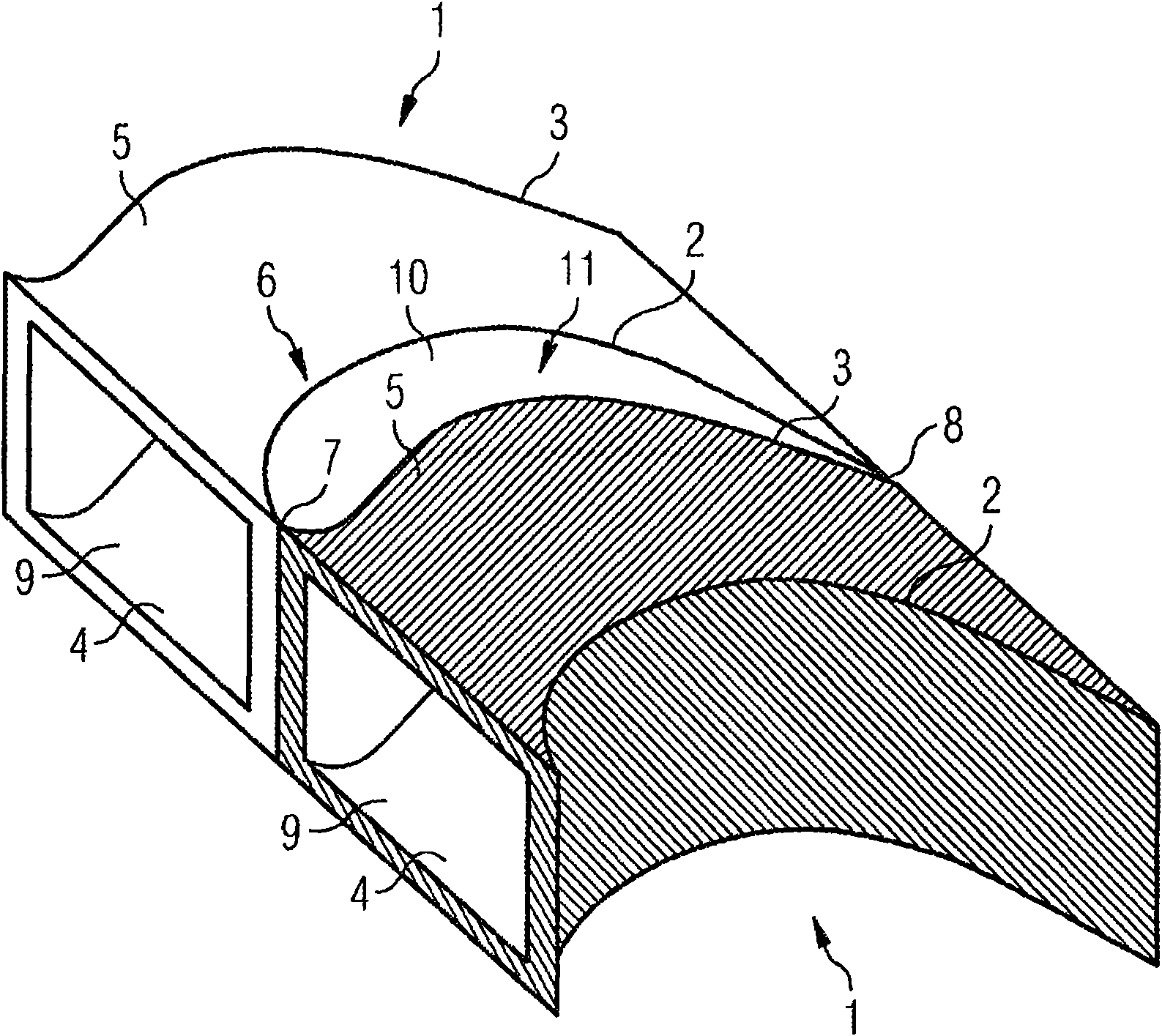
[0050] refer to Figure 1 to Figure 5 , The guide vane duct element 1 includes: a suction side wall 2 , a pressure side wall 3 , a hub segment wall 4 and a shroud segment wall 5 . The pressure side wall 3 is arranged facing the suction side wall 2 and the hub section wall 4 is arranged facing the shroud section wall 5 such that said walls 2 , 3 , 4 , 5 form ducts serving as flow channels 9 .

[0051] according to figure 1 , two separate vane duct elements 1 are arranged side by side such that the suction side wall 2 of one vane duct element 1 and the pressure side wall 3 of the other vane duct element 1 abut each other at least at certain points so as to cooperate to form Guide vane 6. The vane 6 has a leading edge 7 and a trailing edge 8 each formed by mating the suction side wall 2 of one vane duct element 1 and the pressure side wall 3 of the other vane duct element 1 .

[0052] Inside the vane 6 , ie between the suction side wall 2 of one vane duct element 1 and the pre...


PUM


Abstract

An inlet guide vane arrangement for a gas turbine comprises a plurality of guide vane duct elements, the guide vane duct elements comprise a suction side wall (2) and a pressure side wall (3), both walls (2, 3) facing each other, and being designed to be adjoinable to another of said guide vane duct elements (1), such that the pressure side wall (3) of one guide vane duct element (1) cooperates with the suction side wall (2) of the adjacent guide vane duct element (1) thereby forming a guide vane (6), and the guide vane duct element (1) includes features to accept a key element (15) adapted to be arranged between the pressure side wall (3) and the adjacent suction side wall (2), when two guide vane duct elements (1) are adjoining to one another, and to fix together both adjoining guide vane duct elements (1).

Description

technical field [0001] The present invention relates to inlet guide vane arrangements for gas turbine engines. Background technique [0002] Blades, in particular stator blades, in gas turbine engines, especially axial flow gas generator turbines, are subjected to mechanical and thermal loads during operation of the turbine. Thermal and mechanical loads are caused by hot gas flows that heat the blades and apply gas pressure to these blades. Specifically, the first nozzle vanes immediately downstream of the combustion chamber of the gas generator experience hot gas temperatures. [0003] It is highly desirable to design and construct blades with sufficient mechanical integrity to withstand the loads imposed during operation. [0004] In addition, the integrity of the blade also depends on the durability life of the blade. Specifically, blade creep occurs when blades are subjected to high temperatures and strains for extended periods of time, leading to cracks in the blade ...

Claims


Application Information

Patent Timeline
Patent Type & Authority Applications(China)
IPC IPC(8): F01D9/04
CPCF05B2240/12F05B2260/60F01D5/143F05D2240/12F05D2230/61F05B2230/601F05D2260/60F01D9/04F01D9/065F05D2260/2212F05D2260/22141F01D5/18F01D5/32F01D25/12F02C7/12
Inventor M·哈塞尔奎斯特P·西尼尔
Owner SIEMENS AG