Draw-out device

A withdrawable type and installation groove technology, which is applied in the direction of switchgear, transmission device, pull-out switchgear, etc., can solve the problems of destructive danger at the upper end of the circuit breaker body, low reliability of the guiding structure, and increased operating force. Achieve the effect of improving operation safety, reasonable force point and reducing operation force

Active Publication Date: 2012-01-11
BEIJING PEOPLES ELECTRIC PLANT
View PDF4 Cites 0 Cited by
  • Summary
  • Abstract
  • Description
  • Claims
  • Application Information

AI Technical Summary

Problems solved by technology

[0003] In the existing drawer structure, the force point of the circuit breaker body is at the rear and lower, and there is a large resistance when the circuit breaker body enters and exits the drawer. Therefore, this structure easily causes the circuit breaker body to be subject to an overturning moment that rotates around the force point.
This not only increases the operating force and makes the movement unstable, but also easily causes a certain destructive danger to the structure of the upper end of the circuit breaker body
In addition, the guide structure in which the circuit breaker body slides back and forth in the drawer is not reliable and is easily deformed

Method used


Image

  • Draw-out device
  • Draw-out device
  • Draw-out device

Examples


Embodiment Construction

[0026] The present invention will be further described below in conjunction with accompanying drawing.

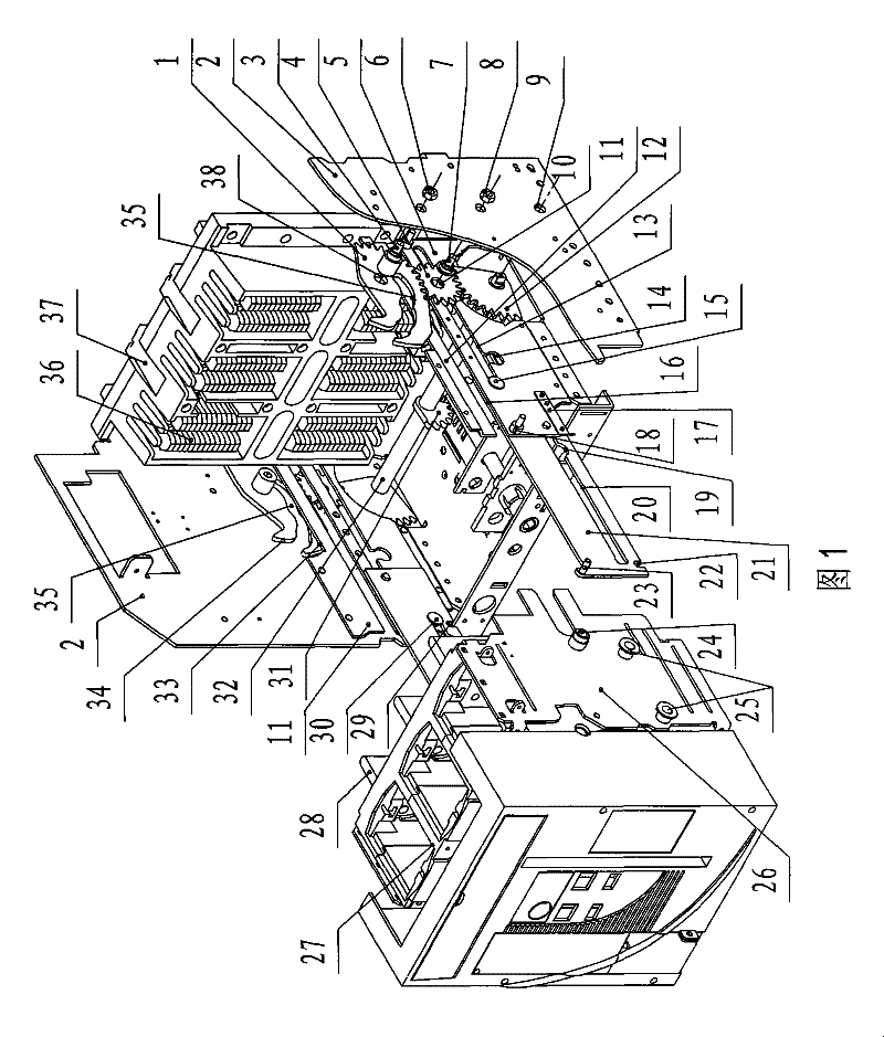
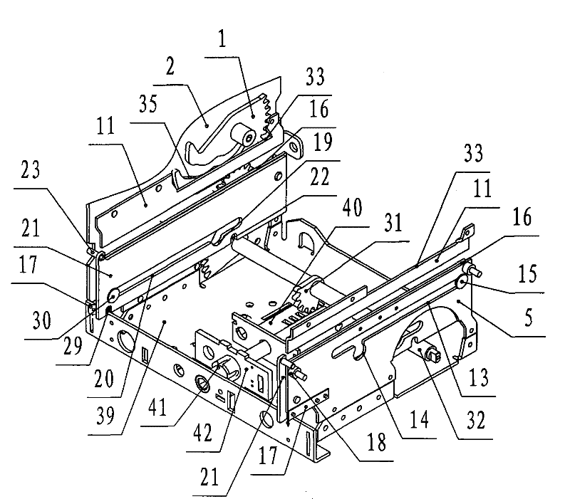
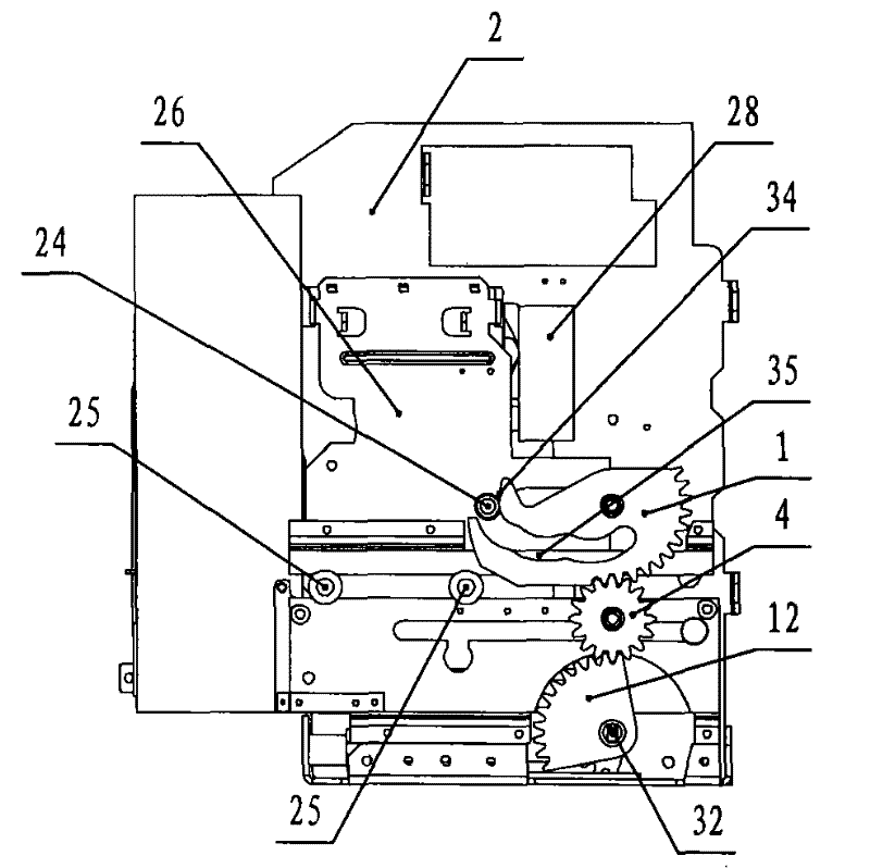
[0027] The present invention is a pull-out device for realizing the drawer-type circuit breaker entering or exiting the drawer, which includes: a pair of side plates 2 placed on the left and right, a rotating shaft 32, two groups of the same structure and symmetrically arranged on the pair of side plates Inside gear transmission mechanism, a pair of upper fixed guide plates 11 , a pair of lower fixed guide plates 5 , a pair of sliding guide plates 21 , and a pair of brackets 26 . in:

[0028] The rotating shaft 32 is installed in the rotating shaft holes 9 of the pair of side plates 2 and can rotate in the rotating shaft holes 9 . A pair of sector gears 31 are installed in the middle of the rotating shaft 32, the pair of sector gears 31 are engaged with the rack plate 40 mounted on the bottom plate 39, the operating screw 41 is installed on the support 42, and is fixed on ...


PUM


Abstract

The invention discloses a draw-out device, which comprises a pair of side plates, a rotating shaft, two sets of gear drive mechanisms having the same structure, two pairs of fixed guide plates, a pair of sliding guide plates and a pair of supports, wherein the rotating shaft is arranged on the side plates; the gear drive mechanisms comprise a pair of driving gear wheels, a pair of intermediate gears and a pair of sector-gear cams having cam slideways, and the driving gears are fixed on the two ends of the rotating shaft and drive the sector-gear cams through the intermediate gears; the upper and lower fixed guide plates are arranged on the inner sides of the side plates, the outer front lower ends of the lower fixed guide plates are fixed with elastic stop pins and a slideway is formed between the upper rand lower fixed guide plates; the sliding guide plates are in front and back sliding connection with the inner sides of the lower fixed guide plates and limiting grooves are arranged in front and at back of the bottom ends of the sliding guide plates; and the supports are fixed on the two sides of an underframe of the body of the breaker and are fixed with upper rollers matched with the cam slideways and lower rollers rolling in the slideway. The device can ensure the reasonable stress, smooth movement and small operating force of the breaker body during the access to a drawerand is safe and reliable in structure.

Description

technical field [0001] The invention relates to a draw-out device, in particular to a device for realizing a drawer-type circuit breaker entering or withdrawing from a drawer. Background technique [0002] The circuit breaker is the most important power distribution equipment in the low-voltage power distribution system, and the drawer circuit breaker is widely used because of its simple and convenient installation and maintenance. At present, with the improvement of scientific design, reliability and humanization requirements, higher requirements are put forward for the withdrawable device of the circuit breaker. The drawer type circuit breaker is composed of a circuit breaker body and a drawer. When the circuit breaker body enters or exits the drawer, it is required that the force position of the circuit breaker body is reasonable, the movement is stable, and the operating force is small. [0003] In the existing drawer structure, the force point of the circuit breaker bo...

Claims


Application Information

Patent Timeline
Patent Type & Authority Patents(China)
IPC IPC(8): H02B11/127H02B11/173F16H1/22
Inventor 南寅宇文丽霞
Owner BEIJING PEOPLES ELECTRIC PLANT
Why Eureka
Try Eureka