Eureka AIR delivers breakthrough ideas for toughest innovation challenges, trusted by R&D personnel around the world.

Multi-camera movable photography measuring method in vibration environment

A measurement method and dynamic photography technology, applied in the field of measurement, can solve the problems of error, the position relationship of multiple cameras cannot be kept fixed, etc.

Inactive Publication Date: 2010-01-20
张征宇
View PDF3 Cites 17 Cited by
  • Summary
  • Abstract
  • Description
  • Claims
  • Application Information

AI Technical Summary

Problems solved by technology

[0005] The ideal measurement method for measuring the position or shape of an object in a vibrating environment is an online measurement system with multiple cameras. However, the positional relationship between multiple cameras in a vibrating environment cannot be kept fixed. Therefore, the external orientation of multi-camera online measurement in a static environment Parameter calculation method, in a vibrating environment, errors will occur due to changes in the distance between cameras
For example, in the current deformation measurement of the wind tunnel model, due to the vibration of the wind tunnel body where the camera is installed, a single camera method is often used, but it can only accurately measure two-dimensional coordinates

Method used


Image

  • Multi-camera movable photography measuring method in vibration environment

Examples


Embodiment Construction

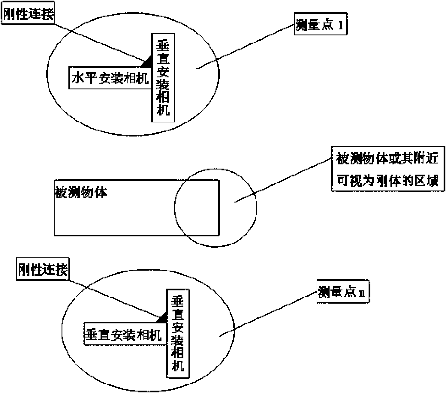
[0018] Such as figure 1 As shown, the specific embodiment of the multi-camera dynamic photogrammetry method in the vibration environment of the present invention includes the following steps:

[0019] a. First, find out the part that does not deform during the measurement process on or near the measured object, that is, the area that is regarded as a rigid body, and paste the coded marking points in the area regarded as a rigid body. The number of coded marking points is greater than or equal to 4 , and the printed coding marks are not in the same plane;

[0020] b. In a vibration-free environment, use static digital industrial photogrammetry technology to measure the three-dimensional coordinates of the sticky-printed code marking points on the area regarded as a rigid body;

[0021] c. In a vibration-free environment, use static digital industrial photogrammetry technology to calibrate the inner orientation elements of multiple cameras;

[0022] d. In a vibrating environme...


PUM


Abstract

The invention discloses a multi-camera movable photography measuring method in a vibration environment, comprising the following steps: printing a coding marker on a measured object or nearby rigid body in a sticky mode, then mounting two digital cameras in rigid connection at each measuring point (one mounted horizontally and the other mounted vertically) to obtain exterior orientation elements of two digital cameras in the measuring points, and then accurately gaining a three-dimensional coordinate of the printed markers on the measured object in the vibration environment through a bundle adjustment computing method. By improving the computing method, the three-dimensional coordinate of the printed markers on the measured object in the vibration environment is gained accurately through the bundle adjustment computing method, rather than a compensation algorithm. Three-dimensional measurement problems of position, shape or movement of the object in the vibration environment are solved, such as accurate measurement of model deformation in a wind tunnel test.

Description

technical field [0001] The invention relates to the technical field of measurement methods, in particular to a multi-camera dynamic photogrammetry method in a vibrating environment. Background technique [0002] Traditional contact measurement, such as three-coordinate measuring machine, has high measurement accuracy (up to about 1 micron), but it is difficult to use in a vibration environment. It requires a special measurement room and a dedicated measurement table. The measurement range is limited and the measurement efficiency is low. [0003] Digital close-range photogrammetry inherits the strict theory and method of traditional photogrammetry, and has high accuracy and reliability, and the hardware facilities are simple (no precision instruments are required except digital cameras), the measurement method is flexible, and it is convenient for on-site non-contact measurement. It is used in the detection of reverse engineering, sheet metal forming analysis, machinery manu...

Claims


Application Information

Patent Timeline
IPC IPC(8): G01C11/00G01B11/00G01B11/24
Inventor 张征宇罗川
Owner 张征宇
Why Eureka
Eureka Blog
Learn More