Check patentability & draft patents in minutes with Patsnap Eureka AI!

Spring operating mechanism

A technology of operating mechanism and pushing part, applied in the direction of high-voltage air circuit breakers, electrical components, electric switches, etc., can solve the problems of inconvenient replacement, easily damaged closing coil, large size, etc., to achieve easy replacement and maintenance, structural Reasonable layout and miniaturization effect

Inactive Publication Date: 2010-01-27
施耐德(陕西)宝光电器有限公司
View PDF9 Cites 12 Cited by
  • Summary
  • Abstract
  • Description
  • Claims
  • Application Information

AI Technical Summary

Problems solved by technology

Taking the currently widely used products as an example, the mechanism mounting plate adopts a welded structure, and the maintenance and replacement of components is complicated and time-consuming
For example, the closing coil is easily damaged during use, and it is inconvenient to replace it
Secondly, the existing mechanism structure is relatively complex and the size is large. With the development of insulating materials and the market demand for miniaturization, it is difficult for VS1 to be directly applied to smaller size requirements.
Take 12kV as an example, the opening distance range of 10-12mm is too large. With the continuous development of vacuum interrupter technology, major manufacturers of interrupter at home and abroad can control it at 6-10mm, which limits the reliability of vacuum circuit breakers. and mechanical life
In the opening buffer treatment, it uses almost the whole process of buffering. If the quality of the oil cup changes during the use process, it may cause serious consequences for the opening

Method used


Image

  • Spring operating mechanism
  • Spring operating mechanism
  • Spring operating mechanism

Examples


Embodiment Construction

[0019] The present invention will be described more fully hereinafter with reference to the accompanying drawings, in which exemplary embodiments of the invention are illustrated.

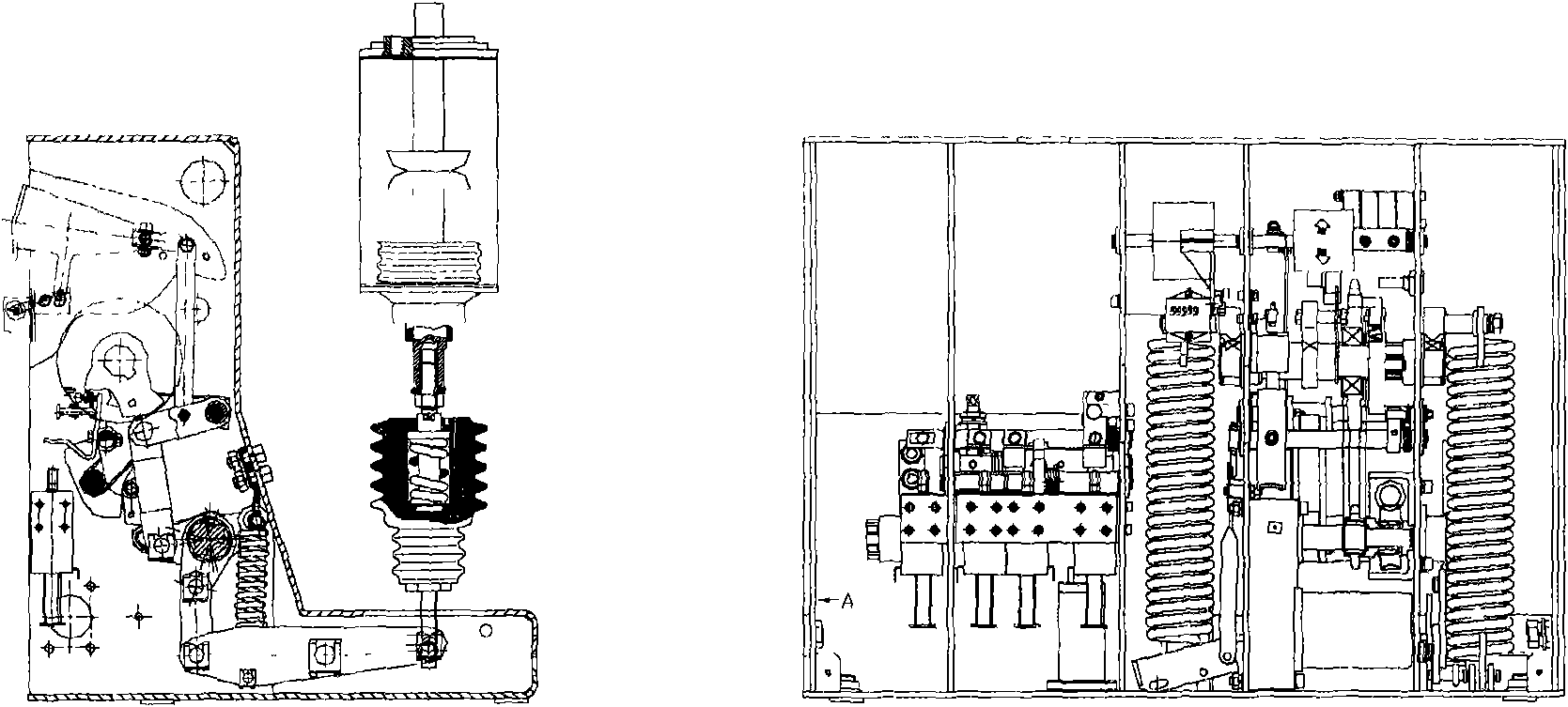
[0020] figure 2 It is a structural front view of an embodiment of the spring operating mechanism according to the present invention. like figure 2 As shown, the spring operating mechanism includes a left plate 17 of the mechanism, a right plate 20 of the mechanism and an intermediate partition 27 of the mechanism, and the intermediate partition 27 of the mechanism is fixed between the left plate 17 of the mechanism and the right plate 20 of the mechanism. The mechanism frame is divided into four areas by the mechanism left plate 17, the mechanism right plate 20 and the mechanism middle partition plate 27. From left to right, they are: energy storage part, closing part, opening part and secondary lead part. This mechanism is bolted with mechanism frame by mechanism left plate 17 and mechanism ri...


PUM


Abstract

The invention discloses a spring operating mechanism comprising a mechanism left board (17), a mechanism right board (20) and a mechanism middle clapboard (27), wherein, the mechanism middle clapboard (27) is fixed between the mechanism left board (17) and the mechanism right board (20), and the mechanism is connected with a mechanism frame by the mechanism left board (17) and the mechanism right board (20).The spring operating mechanism of the invention can be connected with the frame by the mechanism left board and the mechanism right board and takes most components of the operating mechanism as a module capable of be detached from the frame, which facilitates replacement and maintenance of the components and brings convenience for maintaining the spring operating mechanism.

Description

technical field [0001] The invention relates to vacuum circuit breaker technology, in particular to a spring operating mechanism. Background technique [0002] At present, the main circuit breakers in the domestic market have been designed for 10 years from the original design. With the continuous improvement of the design process quality and equipment technology level of the vacuum interrupter, the mechanism has obviously lagged behind. [0003] figure 1 It is a diagram of a spring operating mechanism of the prior art. Taking the currently widely used products as examples, the mechanism mounting plate adopts a welded structure, and the maintenance and replacement of components is complicated and time-consuming. For example, the closing coil is easily damaged during use, and it is inconvenient to replace it. Secondly, the existing mechanism structure is relatively complex and the size is large. With the development of insulating materials and the market demand for miniat...

Claims


Application Information

Patent Timeline
Patent Type & Authority Applications(China)
IPC IPC(8): H01H33/666H01H33/40
Inventor 王科
Owner 施耐德(陕西)宝光电器有限公司
Features
  • R&D
  • Intellectual Property
  • Life Sciences
  • Materials
  • Tech Scout
  • Unparalleled Data Quality
  • Higher Quality Content
  • 60% Fewer Hallucinations
Learn More