
Light box

A light box and point light source technology, which is applied to instruments, lighting and heating equipment, semiconductor devices of light-emitting elements, etc., can solve the problem of uneven illumination on the surface of the light box, suppress the uneven surface illumination, achieve thinning, reduce uneven effect of light

Inactive Publication Date: 2010-02-03
FURUKAWA ELECTRIC CO LTD
View PDF1 Cites 28 Cited by
  • Summary
  • Abstract
  • Description
  • Claims
  • Application Information

AI Technical Summary

Problems solved by technology

[0006] However, since the light emitted by LEDs has strong directivity, when LEDs are arranged on a planar light-reflecting surface, there is a problem in that there are bright spots on the surface of the light box where the light of the LEDs directly reaches, and dark spots where the light does not reach. parts, so that the surface illuminance of the light box is uneven
[0007] If only a concave lens or prism is added in front of the LED to diffuse the emitted light, and only a light reflection plate with a visible light diffusion reflectance of 90% or more is used together with the LED, then for a thinner light box or reduce the number of LEDs There are a large number of light boxes, and there is a problem that the surface illuminance of the light boxes cannot be prevented from being uneven

Method used


Image

  • Light box
  • Light box
  • Light box

Examples


Embodiment 1

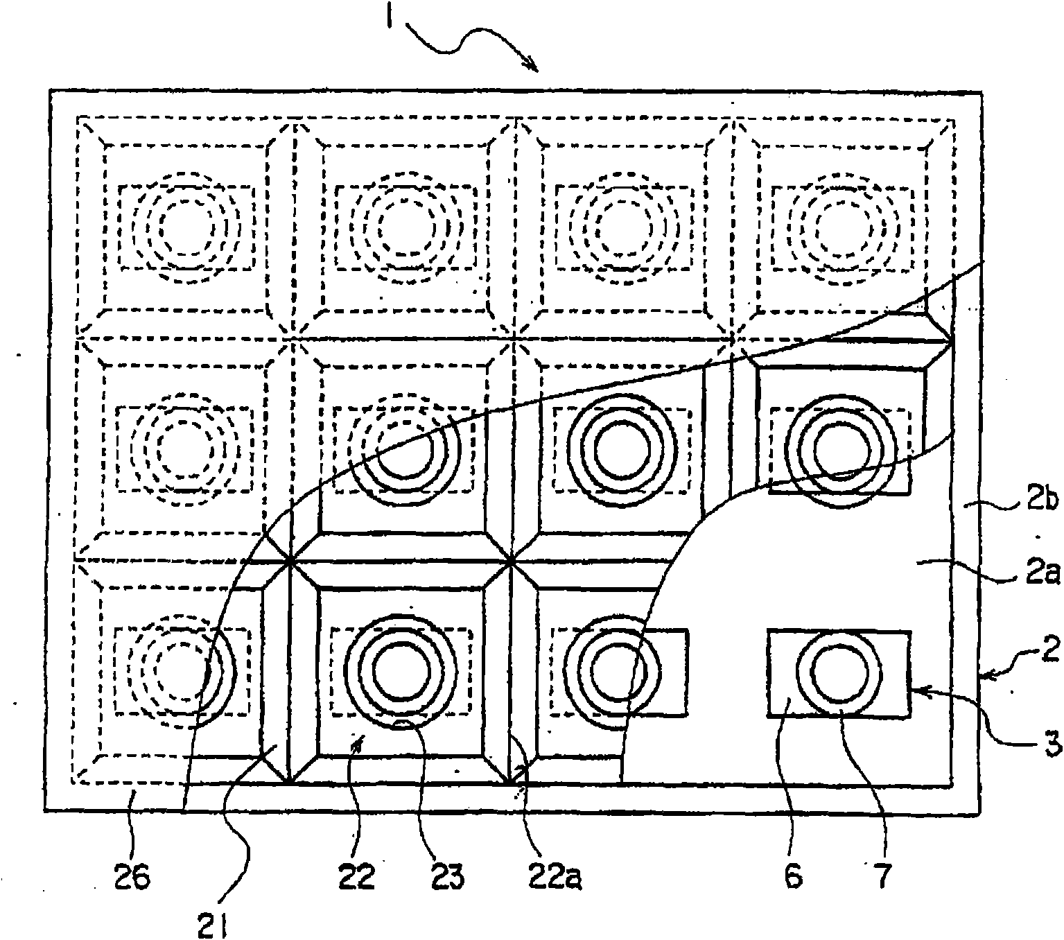
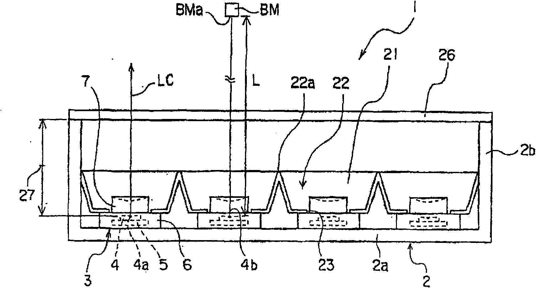
[0095] made figure 1 and figure 2 Light box 1 shown.

[0096] Set shell 2 at figure 1 The longitudinal dimension (inner dimension) shown in the up and down direction of the figure 1 The horizontal dimension (inner dimension) shown in the left and right direction of the is 400mm, in figure 2 The upper and lower directions show a planar rectangular shape with a depth dimension of 60mm for the upper opening. In addition, the thickness dimension of the bottom plate 2a and the side plate 2b was set to 4 mm, respectively. On the upper surface of the bottom plate 2a of the housing 2 (the inner surface of the bottom of the housing 2), three vertically, vertically and horizontally at intervals of 100 mm are arranged in a matrix at intervals of 100 mm in the vertical direction perpendicular to each other. A total of 12 light source modules 3 of 4 in the horizontal direction are used as point light sources.

[0097] As the light source module 3 , Shining Eye (L) (trade name of Ko...


PUM


Abstract

To provide a thin light box employing a light source of strong directivity such as an LED, or a light box in which occurrence of unevenness in surface illuminance is suppressed even when the number ofLEDs is reduced by a factor of 4-9 as compared with prior art. ¢MEANS FOR SOLVING PROBLEMS! The light box (1) comprises a plurality of spot light sources (4), and a light reflector (21) having recesses (22) surrounding the spot light sources (4), respectively. The spot light sources are inserted into insertion holes (23) formed in the bottom of the containing recesses (22), respectively. When theincident angle of light exiting the spot light source (4) is 0 DEG and the spot light sources (4) are spaced apart by 350 mm, the illuminance is 15000 cd / m<2> or less and the light exiting the spotlight source (4) is reflected partially or entirely on the inner surface of the containing recesses (22) before offering illumination.

Description

technical field [0001] The present invention relates to a light box, and more particularly to an interior-illuminated light box using point light sources such as LEDs (Light Emitting Diodes), and more specifically, to an interior-illuminated light box applicable to electric signboards, interior-illuminated signs, and liquid crystal display devices. Light boxes for backlights and lighting fixtures. Background technique [0002] Conventionally, straight tube-shaped light sources such as fluorescent lamps and cold-cathode tubes have been used in interior-illuminated light boxes. However, the service life of fluorescent lamps is relatively short. For example, for a 40W ordinary straight tube fluorescent lamp, its service life is about 12,000 hours. Since the fluorescent lamps are replaced every time they are disconnected, the fluorescent lamps are replaced at the same time once a year. However, there is a problem that it is necessary to work at high places at night. [0003] I...

Claims


Application Information

Patent Timeline
Patent Type & Authority Applications(China)
IPC IPC(8): F21S2/00H01L33/00F21V7/00H01L33/54H01L33/56
CPCF21K9/00G02F1/133603G02F1/133605H01L33/58F21K9/68
Inventor 大出谦石井俊司池田英行
Owner FURUKAWA ELECTRIC CO LTD
Learn More