
Brush head device for electronic toothbrush

An electric toothbrush and brush head technology, applied in dentistry, cleaning teeth, medical science and other directions, can solve the problems of wear of the inner wall of the hollow sleeve, affecting the comfort and service life of the toothbrush head, and the loose connection between the toothbrush head and the rotating shaft sleeve, etc. Achieve the effect of improving service life and quality

Inactive Publication Date: 2010-02-10
黄拔梓
View PDF1 Cites 8 Cited by
  • Summary
  • Abstract
  • Description
  • Claims
  • Application Information

AI Technical Summary

Problems solved by technology

[0002] The current electric toothbrush is composed of a motor, a rotating shaft, a toothbrush head, a tooth handle and other components. The lower end of the toothbrush head is provided with a hollow sleeve, which is directly connected to the front end of the rotating shaft. The rotation and vibration of the rotating shaft drives the vibration and swing of the front end of the toothbrush head. To achieve the purpose of automatically cleaning the teeth, but there are the following defects in this socketing method. The hollow sleeve at the lower end of the toothbrush head is made of hard plastic material, and the rotating shaft is made of metal material. The hollow sleeve and the rotating shaft at the lower end of the toothbrush head are rigid. Connection, long-term use will gradually wear the inner wall of the hollow sleeve, making the socket connection between the toothbrush head and the rotating shaft loose, which will affect the comfort and service life of the toothbrush head

Method used


Image

  • Brush head device for electronic toothbrush
  • Brush head device for electronic toothbrush

Examples


Embodiment Construction

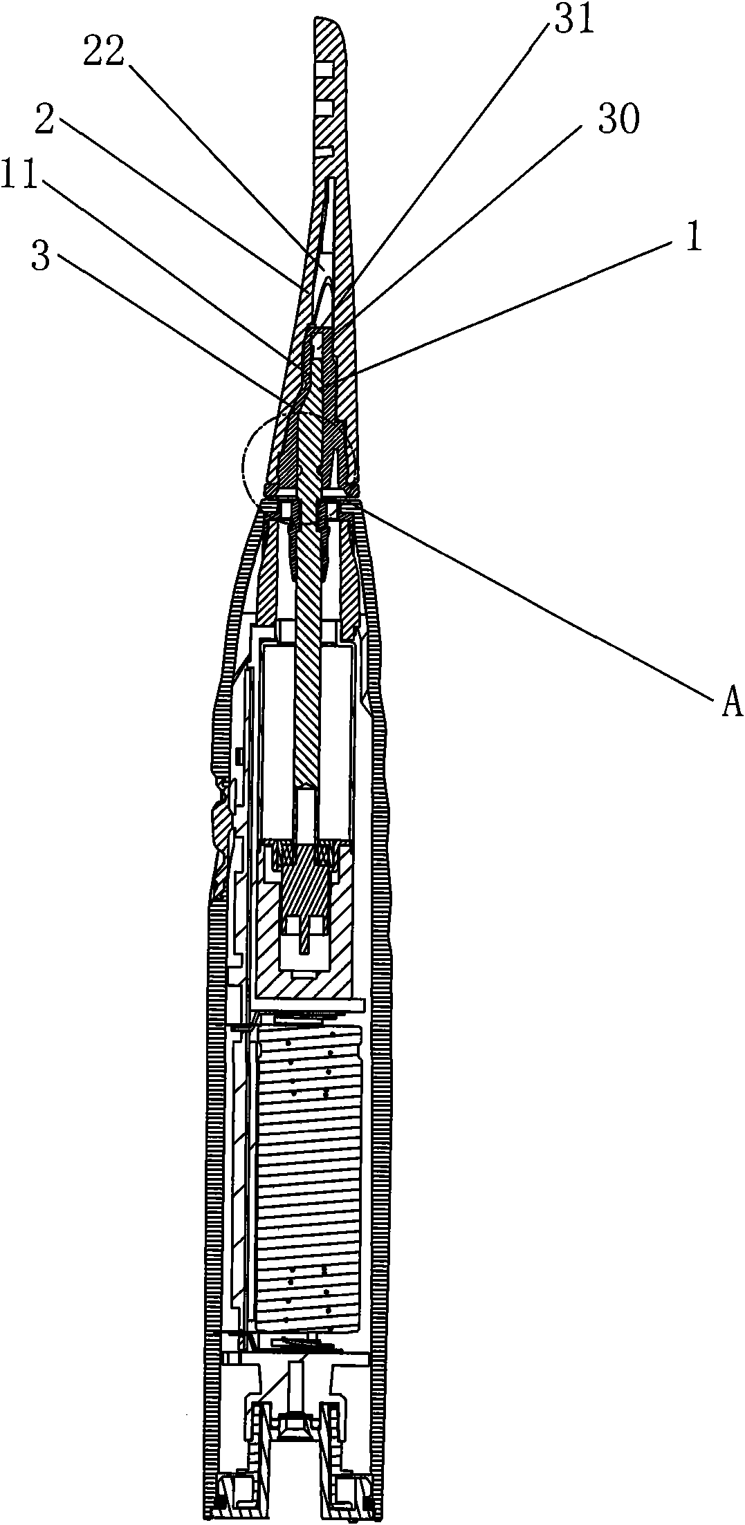
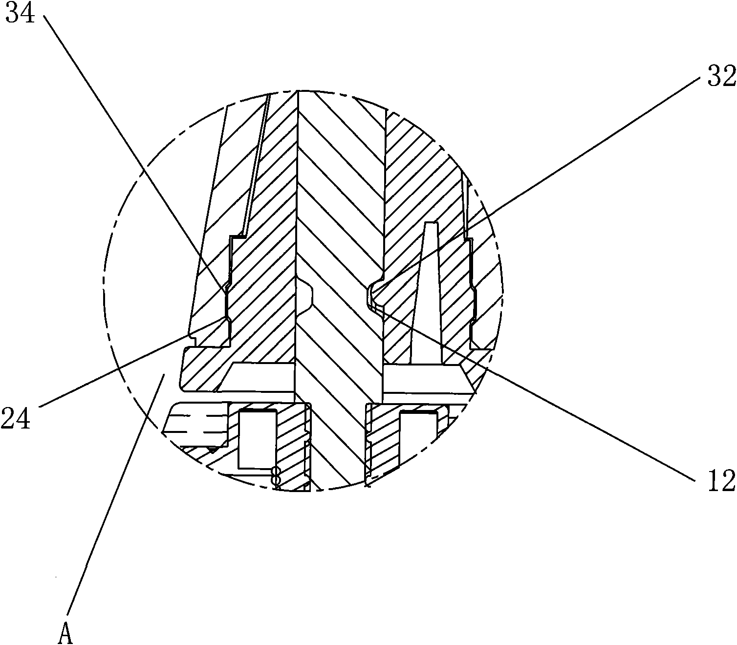
[0009] refer to figure 1 , figure 2 A kind of electric toothbrush brush head device shown, comprises rotating shaft 1, toothbrush brush head 2, is provided with brush head plug 3 between this rotating shaft 1 and toothbrush head 2, and the longitudinal section of this brush head plug 3 is generally irregular conical Shape, the brush head plug 3 is provided with an inner cavity 30 corresponding to the shape of the upper end of the rotating shaft 1, and the upper end of the inner cavity wall is provided with an inner cavity flat position 31 to prevent the brush head from shaking left and right to generate noise, and the corresponding inner cavity flat position The upper end of the rotating shaft is provided with a flat position 11 of the rotating shaft, and the flat position 31 of the inner cavity is tightly clamped with the flat position 11 of the rotating shaft. The circumferential surface of the shaft 1 corresponding to the flange is provided with a first buckle groove 12 i...


PUM


Abstract

The invention discloses a brush head device for an electronic toothbrush. The device comprises a rotating shaft and a toothbrush head, wherein a brush head plug is arranged between the rotating shaftand the toothbrush head, and is provided with an inner cavity which corresponds to the shape of the upper end of the rotating shaft; the upper end of the inner cavity wall is provided with a flat partof the inner cavity; the upper end of the rotating shaft corresponding to the flat part of the inner cavity is provided with a flat part of the rotating shaft; the lower end of the inner cavity wallis provided with a first hook flange protruding inwards; the circumference surface of the rotating shaft corresponding to the first hook flange is provided with a first hook groove recessing inwards;and the first hook flange and the first hook groove are closely buckled. The wearable brush head plug arranged between the metal rotating shaft and the brush head of the hard plastic toothbrush solvesthe problem that an electric toothbrush has large abrasion all the time for a long time to cause the joint of the toothbrush head and the upper end of the rotating shaft to get loose, and improves the service life and the quality of the electronic toothbrush.

Description

technical field [0001] The invention relates to an electric toothbrush, in particular to an electric toothbrush brush head device. Background technique [0002] The current electric toothbrush is composed of a motor, a rotating shaft, a toothbrush head, a tooth handle and other components. The lower end of the toothbrush head is provided with a hollow sleeve, which is directly connected to the front end of the rotating shaft. The rotation and vibration of the rotating shaft drives the vibration and swing of the front end of the toothbrush head. To achieve the purpose of automatically cleaning the teeth, but there are the following defects in this socketing method. The hollow sleeve at the lower end of the toothbrush head is made of hard plastic material, and the rotating shaft is made of metal material. The hollow sleeve and the rotating shaft at the lower end of the toothbrush head are rigid. Connection, long-term use will gradually wear the inner wall of the hollow sleeve,...

Claims


Application Information

Patent Timeline
Patent Type & Authority Applications(China)
IPC IPC(8): A61C17/22
CPCA61C17/222
Inventor 黄拔梓
Owner 黄拔梓
Learn More