
Automatic sealing device of spiral tubes

An automatic sealing and lamp tube technology, applied in the direction of electric tube/lamp closing, etc., can solve the problems of poor working conditions and low quality of sealing of spiral lamp tubes, and achieve the effects of compact structure, improved work efficiency, and improved sealing quality

Inactive Publication Date: 2010-02-10
外商独资镇江金品机械有限公司
View PDF0 Cites 9 Cited by
  • Summary
  • Abstract
  • Description
  • Claims
  • Application Information

AI Technical Summary

Problems solved by technology

[0003] The purpose of the present invention is to overcome the shortcomings of low sealing quality and poor working conditions of the manual operation of the spiral lamp tube, and provide an automatic welding device for the spiral lamp tube mouth and the stem cap edge, which can significantly improve the quality of the spiral lamp tube. Improve the sealing quality of the mouth and reduce the labor intensity of the operator

Method used


Image

  • Automatic sealing device of spiral tubes
  • Automatic sealing device of spiral tubes
  • Automatic sealing device of spiral tubes

Examples


Embodiment Construction

[0018] The present invention will be further described below with reference to the drawings and embodiments.

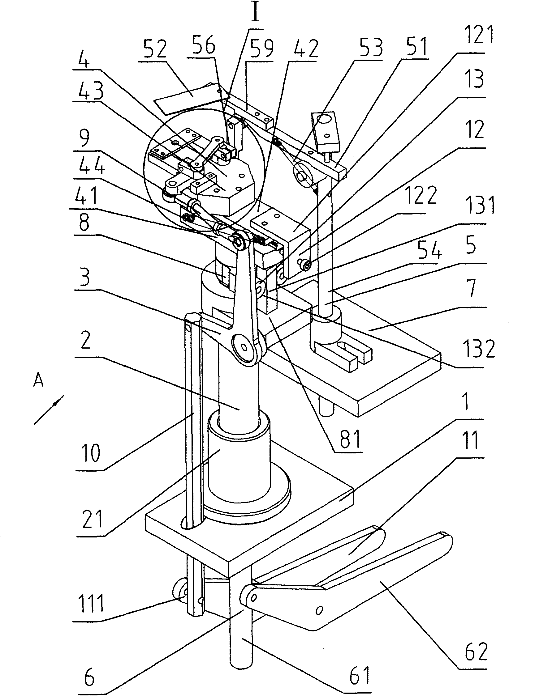
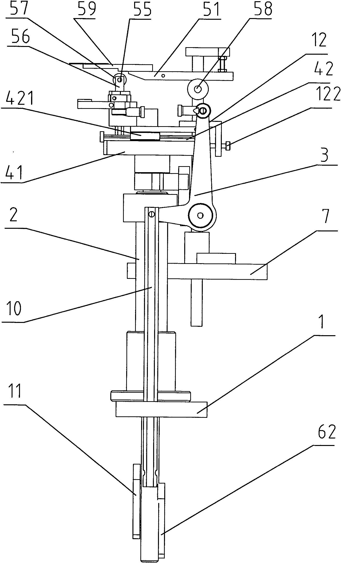
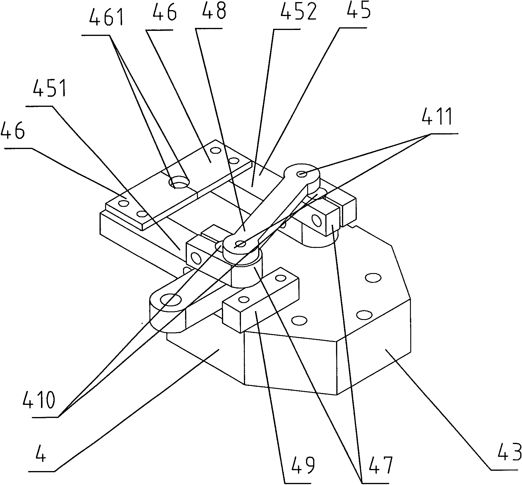
[0019] Such as Figure 1 ~ Figure 3 As shown, the present invention includes a base 1, a column 2, a driving arm 3, a clamping and moving mechanism 4, a lamp tube mechanism 5, a base lifting mechanism 6, a limit mechanism 12, and an anti-rotation mechanism 13; the column 2 is sleeved in France In the flange tube 21, the flange tube 21 is fixedly installed on the base 1, the fixed plate 7 is arranged on the base 1, and the front side of the flange tube 21 supports the clamping and moving mechanism 4 through the supporting column 8. The driving arm 3 is a curved arm with the center lines of the two ends at 90°, and is arranged on one side of the fixed plate 7. The middle part is hinged with one side of the extension section 81 of the support column 8, the upper end is hinged with one end of the connecting rod 9, the lower end is hinged with the upper end of the tie rod 10...


PUM


Abstract

The invention discloses an automatic sealing device of spiral tubes, comprising a base, an upright post, an actuating arm, a clamping mobile mechanism, a tube pressing mechanism and a base lifting mechanism. The upright post is arranged on the base, the upper end of which is provided with a fixed plate; the front side of the fixed plate supports the clamping mobile mechanism through a support post. The middle part of the actuating arm is hinged with one side of the fixed plate, the upper end of which is hinged with one end of the connecting rod, and the lower end of which is hinged with the upper end of a pulling rod; and the other end of the connecting is hinged with one side of the clamping mobile mechanism. The tube pressing mechanism is arranged on the fixed plate through a vertical rod, and the base lifting mechanism is arranged downside the base. The rear part of the clamping mobile mechanism is provided with a limiting mechanism and an anti-rotating mechanism. The automatic spiral tube sealing device of the invention has compact structure, can realize full-automatic sealing of mouth of the spiral tube, significantly improves sealing quality and working efficiency of mouth ofthe spiral tube, and greatly reduces working intensity of operators.

Description

Technical field [0001] The invention relates to an energy-saving lamp manufacturing equipment, in particular to an automatic welding and sealing device for a spiral lamp tube stem and a lamp tube mouth, belonging to the technical field of lamp manufacturing machinery. Background technique [0002] At present, in the sealing process of spiral energy-saving lamps, the stem is first placed vertically in a special tooling, and the cap of the stem is heated from below the stem to 600-700℃ with flame, and then the operator holds the spiral lamp from the top Press down to weld the spiral tube nozzle and the cap edge of the stem into a whole. Due to the difference in the magnitude and repeatability of the manual operation, the welding position and quality of the spiral lamp tube nozzle and the cap edge of the stem are difficult to maintain, and the manual operation efficiency is low. The operator works for a long time under the flame baking. The working conditions are poor. Summary of ...

Claims


Application Information

Patent Timeline
Patent Type & Authority Applications(China)
IPC IPC(8): H01J9/40
Inventor 朱正雄朱育纬
Owner 外商独资镇江金品机械有限公司
Learn More