Flyer shield structure of roving machine

A protective cover and roving frame technology, applied in textiles and papermaking, etc., can solve problems such as affecting high-speed operation, easily staining the flyer, and injury to the operator's pressing palm

Inactive Publication Date: 2010-02-24
JIANGSU KAIGONG MACHINERY
View PDF0 Cites 4 Cited by
  • Summary
  • Abstract
  • Description
  • Claims
  • Application Information

AI Technical Summary

Problems solved by technology

In the prior art, the high-speed rotating operation of the flyer is directly exposed to the outside world. When the flyer is running at high speed, the operator may be injured when touching the pressing palm, and after running at high speed for too long, the pressing palm at the lower part of the flyer may Accidents due to loose or worn parts will cause damage to the operating environment and operators, and the working environment of the roving frame is full of impurities such as cotton and wool. The flyer may be easily stained with these impurities to affect its high speed. run

Method used


Image

  • Flyer shield structure of roving machine
  • Flyer shield structure of roving machine

Examples


Embodiment Construction

[0013] The specific structure of the present invention will be further described below in conjunction with the accompanying drawings.

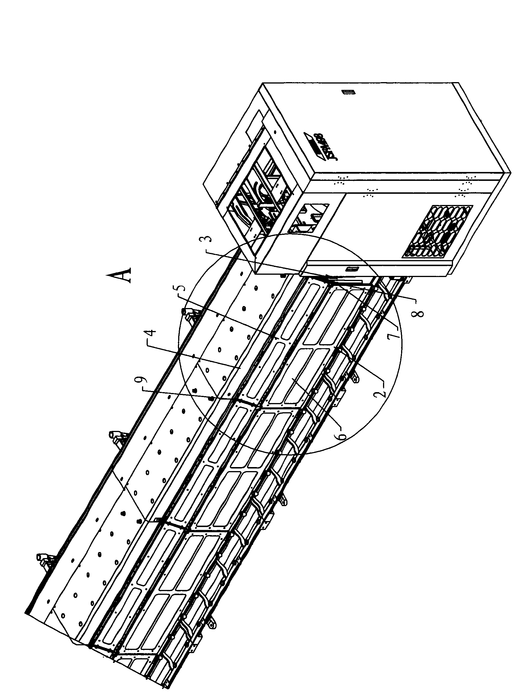
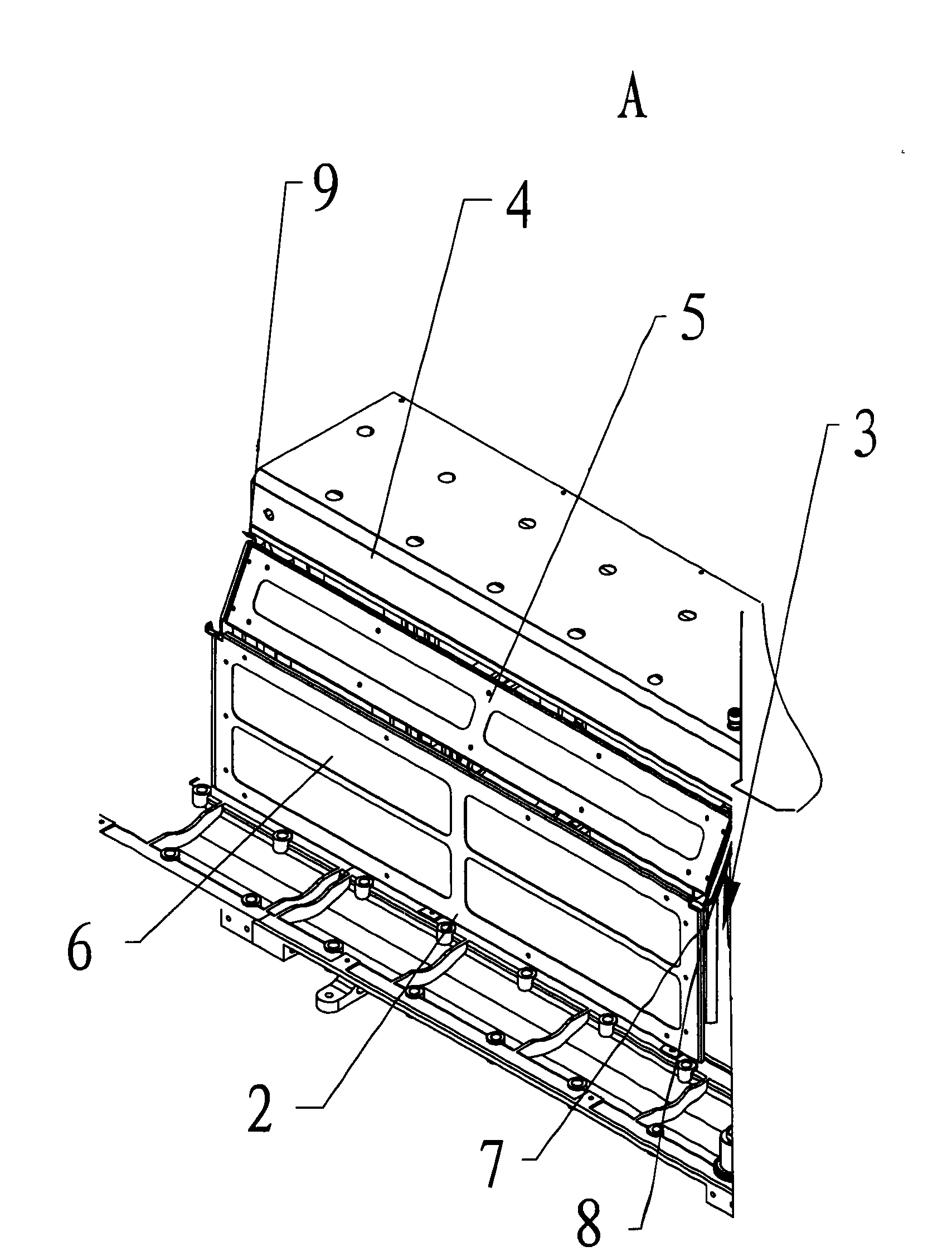
[0014] A flyer protective cover structure on a roving frame, used to prevent the flyer from being directly exposed to the outside during high-speed operation, the structure includes a front protective cover 2 arranged in front of the flyer, and the upper rib plate 4 on the roving frame is equipped with a flyer , the top of the flyer is fixed on the lower part of the upper rib plate 4, as attached Figure 1-2 As shown, on the roving frame, there is an upper protective cover 5 that is arranged on the front and upper side of the flyer. The top edge of the upper protective cover 5 is fixedly installed on the upper rib plate 4 through the connecting bracket 9, and the upper protective cover 5 is inclined. figure 1 As shown, the top edge of the front protective cover 2 is rotatably installed on the bottom edge of the upper protective cover 5, and th...


PUM


Abstract

The invention discloses a flyer shield structure of a roving machine. The roving machine is provided with a pliosaur slat and a flyer of which top end is arranged on the lower part of the pliosaur slat. The flyer shield structure comprises a front shield arranged on the front part of the flyer. The top side of the front shield is rotationally arranged on the roving machine. The front shield is provided with an observational part which is made of transparent or semitransparent materials. A locking mechanism is arranged between the front shield and the roving machine. When the roving machine isoperated normally, the locking mechanism makes the front shield cover on the front part of the flyer. The locking mechanism prevents an operator from being hurt by contacting a press palm, and prevents other accidents caused by blocking the press palm on the flyer or other elements from being thrown down. The locking mechanism can also prevent dust, cotton wool and other impurities from contactingthe flyer. The front shield is provided with the observational part, so the shield plays a role in safety protection. Simultaneously, the shield does not influence the operator to observe the operation condition of the roving machine at any time, and judge the abnormal condition of the roving machine operating abnormally.

Description

technical field [0001] The invention relates to a protective cover structure applied to a roving frame flyer. Background technique [0002] The roving frame is mainly composed of a feeding mechanism, a drafting mechanism, a twisting and winding mechanism, and a winding and forming mechanism. When the roving frame is working, the yarn slivers are led out from the rear can of the machine, actively conveyed by the guide roller, and enter the nip of the rear roller through the guide roller and sliver guide. The drafting mechanism adopts a four-roller device. The fibers in the sliver are drafted under the elastic control of the apron, and the drafted sliver is sent out by the front roller nip, and then aggregated by the collector, and twisted by the flyer. Winded onto bobbin. Relying on the function of the forming mechanism, the upper dragon tendons and the bobbin move up and down according to a certain rule, and the roving is wound into a roving bobbin with tapered ends. In t...

Claims


Application Information

Patent Timeline
IPC IPC(8): D01H7/24
Inventor 苏善珍陈兆琦殷强胡荣朝
Owner JIANGSU KAIGONG MACHINERY
Why Eureka
Try Eureka