

Painting system
A painting and painting booth technology, applied in the direction of spraying device, manipulator, painting booth, etc., can solve the problem of inability to provide painting system, and achieve the effect of shortening painting time, continuous painting, and realizing painting time.
- Summary
- Abstract
- Description
- Claims
- Application Information
AI Technical Summary
Problems solved by technology
Method used
Image

Examples
Embodiment 1
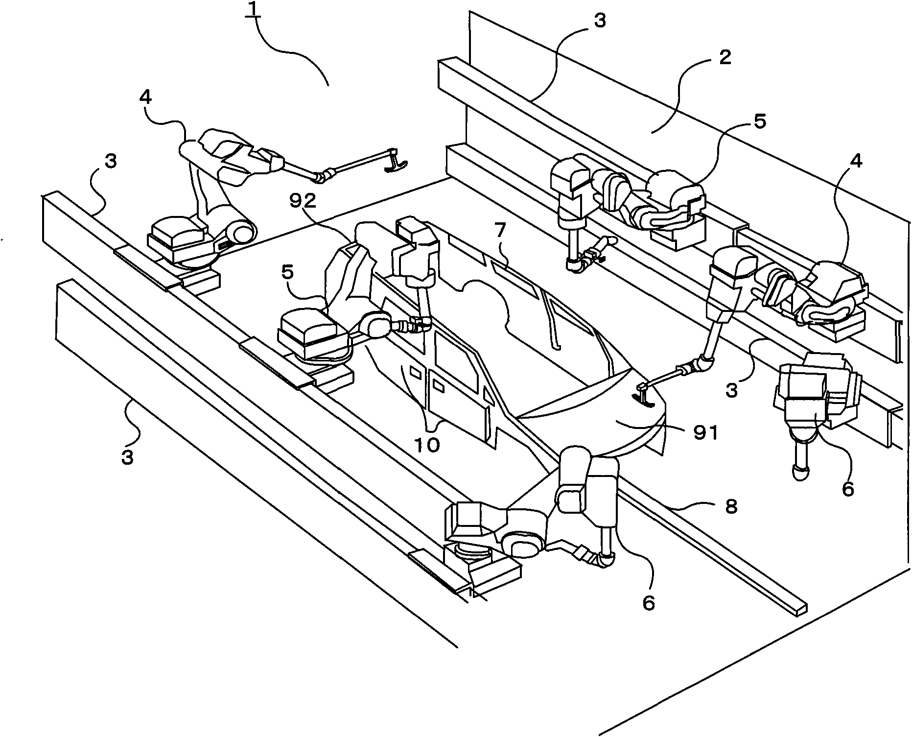
[0057] figure 1 It is a perspective view of the painting system of this invention. 1 is the painting system, 2 is the painting booth, 3 is the moving guide rail, 4 is the box opening tool robot, 5 is the door opening and closing painting robot, 6 is the box painting robot, 7 is the car body, and 8 is the transmission line.
[0058] The difference between the present invention and the conventional example is that a box opener robot 4 is arranged on the moving guide rail 3 of the upper section, and a box painting robot 6 is arranged on the moving guide rail 3 of the lower section. The tank painting robot 6 arranged on both sides is arranged at a position facing the door opening and closing painting robot 5 , and the box opener robot 4 is arranged at a point-symmetrical position centered on the vehicle body 7 .
[0059] In the painting system 1 of the present invention, a vehicle body 7 is mounted on a conveying line 8 , and moving guide rails 3 with different vertical heights ...
Embodiment 2
[0068] Figure 4 It is a perspective view of the painting system of the second embodiment. Parts different from the first embodiment will be described. The difference between the present invention and the first embodiment is that the two box painting robots 6 arranged on the moving guide rails 3 of the lower sections of the two side walls of the painting booth 2 are arranged at point-symmetrical positions with the car body 7 as the center. . Since the configuration of the other painting system 1 is the same as that of the first embodiment, description thereof will be omitted.
[0069] Next, the painting process will be described using the 4-door vehicle body 7 . First, two box opener robots 4 open the engine case 91 in front of the vehicle body 7 in the direction of travel and the trunk 92 in the rear of the vehicle body 7 in the direction of travel, and two door opening and closing painting robots 5 open the front sides of the vehicle body 7. door 10.
[0070] Afterwards...
Embodiment 3
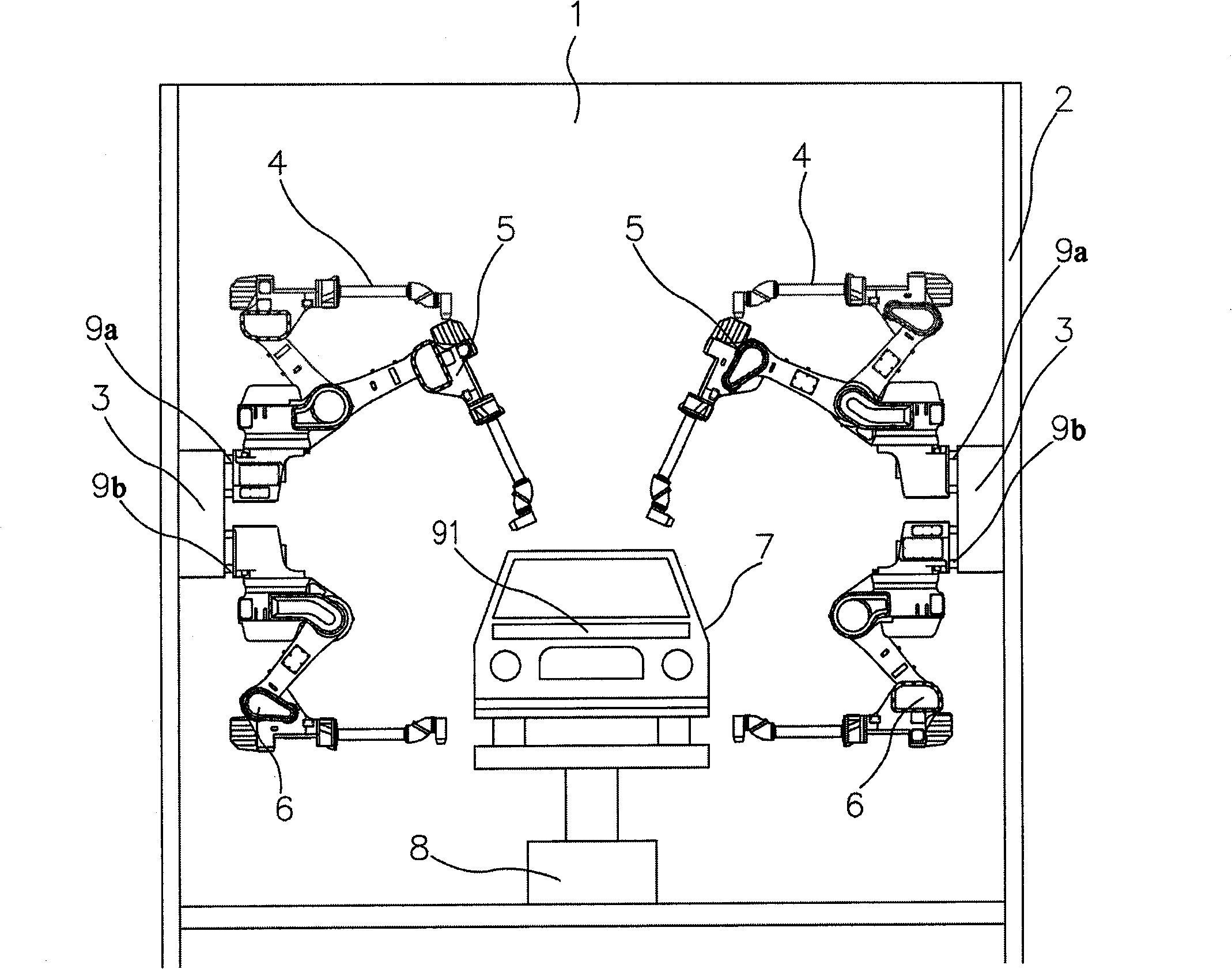
[0077] Figure 5 It is the front view of the painting system of the 3rd embodiment, Figure 6 It is a top view of the painting system of 3rd Example. 1 is the painting system, 2 is the painting booth, 3 is the moving guide rail, 9a, 9b are the guide rails, 4 is the box opening tool robot, 5 is the door opening and closing painting robot, 6 is the box painting robot, 7 is the car body , 8 is the transmission line.
[0078] The difference between the present invention and embodiment 1 and embodiment 2 is that a moving guide rail 3 is arranged above the wall surface of the painting booth 2, and guide rails 9a and 9b are respectively arranged up and down. The box opener robot 4 is arranged on the guide rail 9a of the upper section, and the box painting robot 6 is arranged on the guide rail 9b of the lower section. The closed painting robot 5 is arranged at the opposite position, and the box opener robot 4 is arranged at a point-symmetrical position centered on the car body 7. T...
PUM
 Abstract
Description
Claims
Application Information