Engagement chain

A meshing and sprocket technology, which is applied in the field of meshing chains, can solve the problems of reduced buckling strength of the meshing chain 500, inability to ensure the rigidity of the meshing chain 500, and shaking of the chain plate 550, so as to suppress shaking, realize light weight, and avoid overload Effect

Active Publication Date: 2013-05-22
TSUBAKIMOTO CHAIN CO
View PDF1 Cites 0 Cited by
  • Summary
  • Abstract
  • Description
  • Claims
  • Application Information

AI Technical Summary

Problems solved by technology

[0005] However, in the conventional interlocking chain 500 , since the above-mentioned gap is generated between the buckling restricting flat surfaces 551 , each link plate 550 wobbles or buckles along the opposing link plates 550 . Since the relative deviation of the flat surface 551 is limited, the rigidity of the pair of meshing chains 500 meshing with each other cannot be ensured, and the buckling strength of the pair of meshing chains 500 decreases.
[0006] Furthermore, regarding the problems related to the reduction of the buckling strength of the pair of meshing chains 500 caused by the gap generated between the buckling limiting flat surfaces 551, when the ground is described in Japanese Patent No. 3370928 When the meshing chain 500 is used in the driving device of the placement installation method provided on the installation surface, the buckling restriction flat surface 551 can be generated by the weight of the load bearing member or the driven object acting on the pair of meshing chains 500 . However, when the engaging chain 500 is used in a drive device of a pendant installation type with a ceiling surface as an installation surface or a cantilever support type drive device with a vertical wall as an installation surface, the above-mentioned problem becomes significantly

Method used


Image

  • Engagement chain
  • Engagement chain
  • Engagement chain

Examples


Embodiment

[0037] Hereinafter, the meshing chain 100 which is one Example of this invention is demonstrated based on drawing.

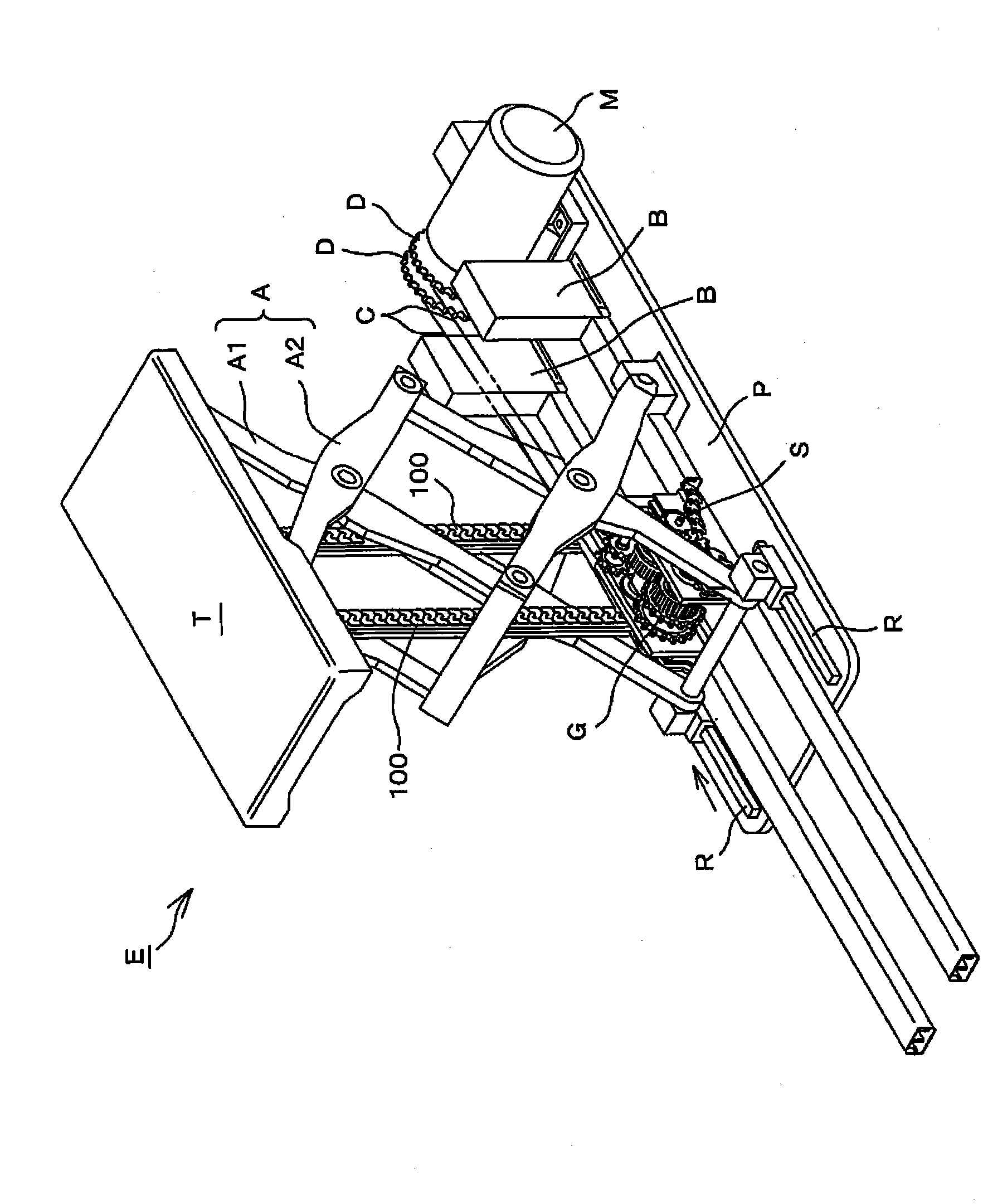
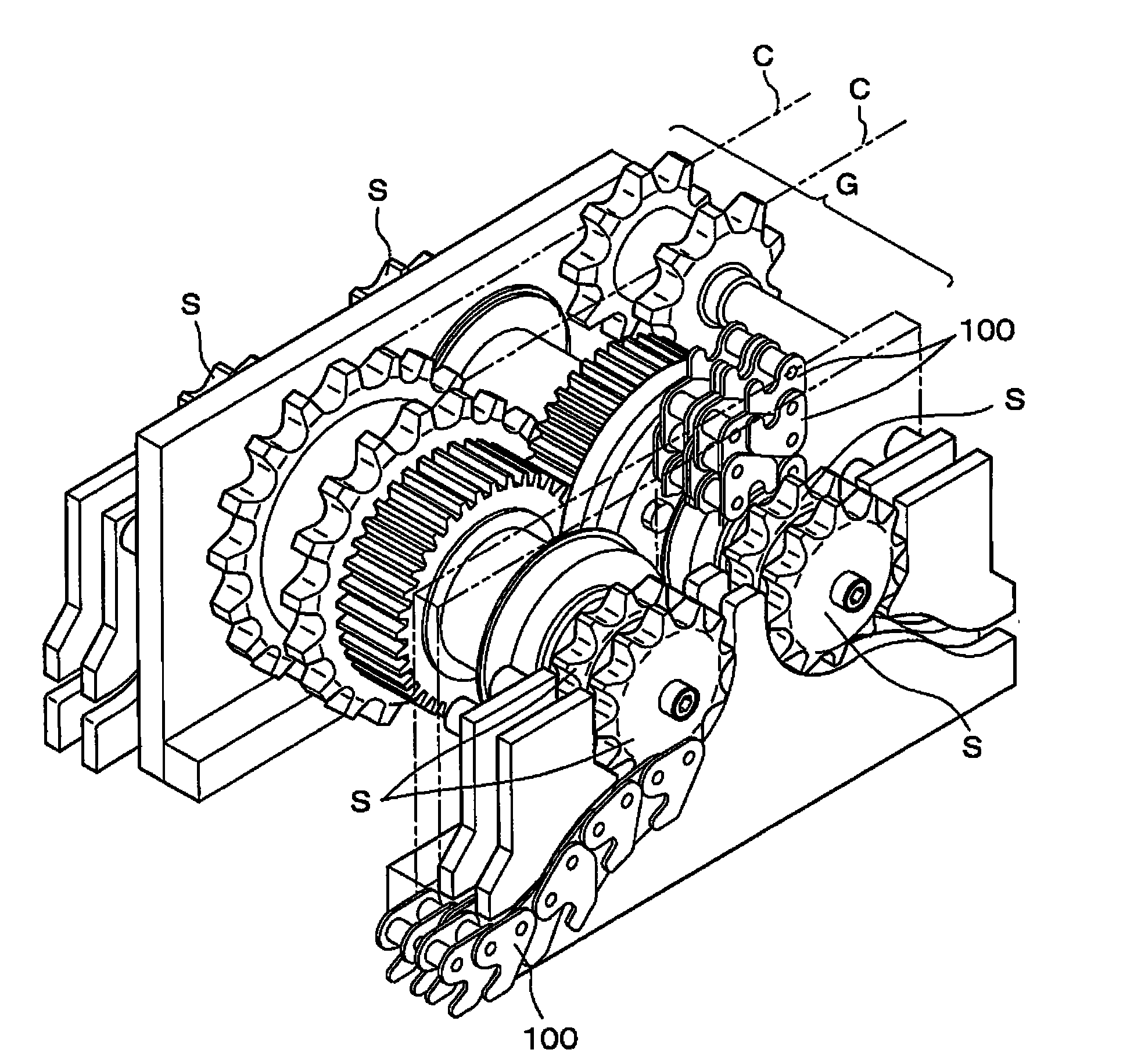
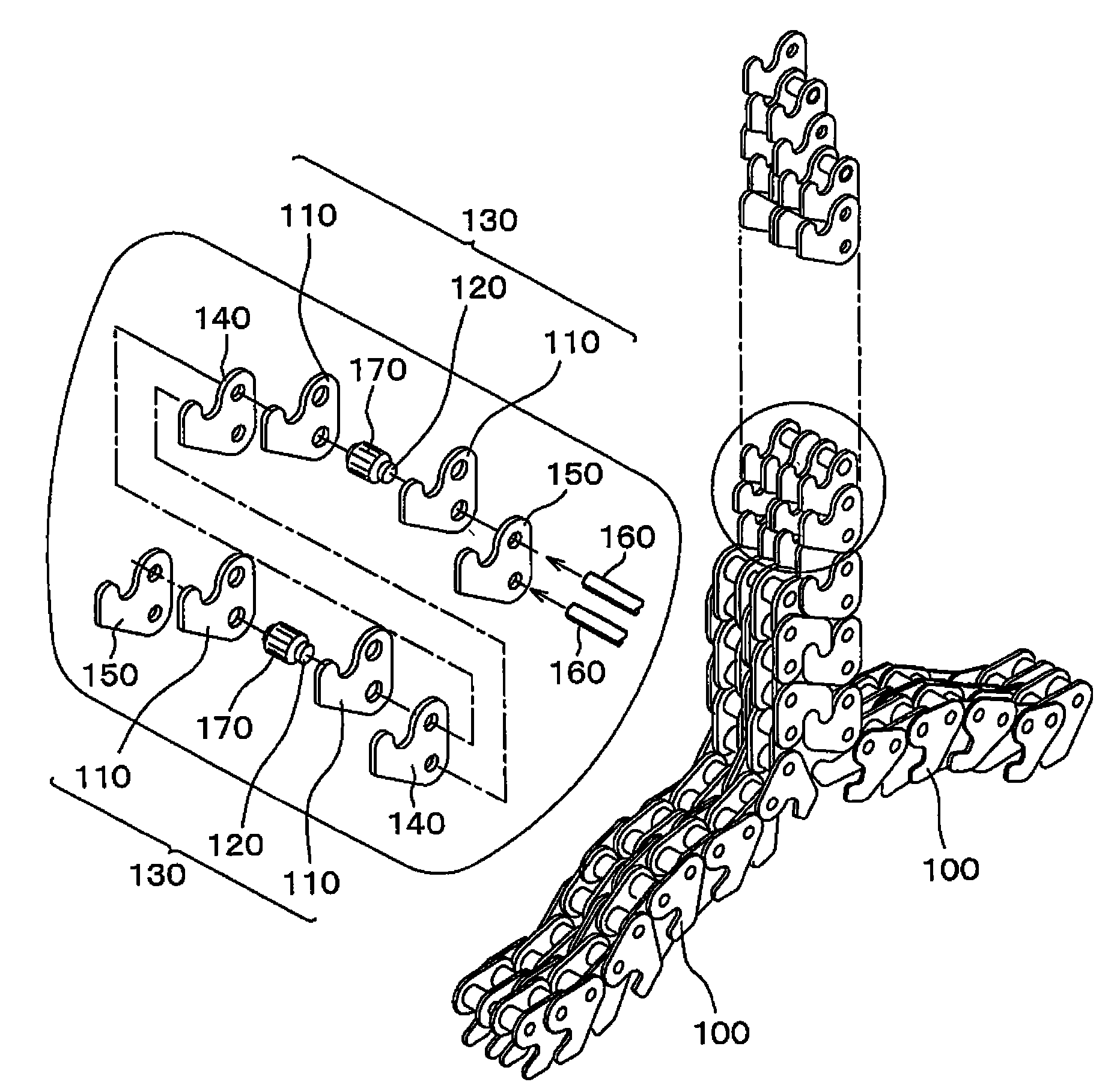
[0038] here, figure 1 It is a usage form diagram using the meshing chain as an embodiment of the present invention, figure 2 From figure 1 A perspective view of the state without the lifting table and the telescopic arm, image 3 is a partial enlarged view showing the meshing chain, Figure 4 is a partial sectional view showing the meshing chain, Figure 5 is a plan view showing the intermeshing external teeth, Figure 6 It is an explanatory diagram showing the state when the external gear pieces start meshing with each other, Figure 7 is an explanatory diagram showing a state in which the external gear pieces mesh with each other, Figure 8 It is an explanatory diagram showing a state in which the external gear pieces mesh with each other.

[0039] First, if figure 1 As shown, the meshing chain 100 as an embodiment of the present invention is assem...


PUM


Abstract

An engagement chain in which a buckling strength of a pair of engagement chains engaged with each other is improved without blocking engagement operations between inner tooth plates and between outer tooth plate. The chain includes inner tooth plates, bushes, outer tooth plates and connecting pins. Buckling limiting flat surfaces of adjoining plates are brought into surface contact with each other when opposing segments of the chain are integrated together by driving sockets.

Description

technical field [0001] The present invention relates to an engaging chain assembled in a driving device used in manufacturing equipment in various manufacturing fields, conveying equipment in the transportation field, nursing equipment in the field of medical welfare, stage equipment in the field of art, etc., so that the driven The object moves forward and backward parallel to the installation surface. Background technique [0002] Conventionally, there has been a drive device that moves a driven object such as a heavy object up and down using a pair of meshing chains that engage with each other and move up and down integrally, that is, a so-called chuck chain (for example, refer to Patent Document 1). [0003] In this conventional meshing chain 500, various studies have been made on the shape of the hook-like surface 552 formed on each link plate 550, the pin pitch, and the bushing pitch, etc., but the buckling limiting flat surface 551 has not yet received attention, and...

Claims


Application Information

Patent Timeline
Patent Type & Authority Patents(China)
IPC IPC(8): B66F3/00
CPCB66F7/0666B66F3/06F16G13/20F16G13/04F16G13/06
Inventor 须子友男中西耕平佐治智之
Owner TSUBAKIMOTO CHAIN CO
Why Eureka
Try Eureka