Battery case for vehicle

A battery and vehicle technology, applied in the direction of batteries, vehicle parts, battery pack parts, etc., can solve the problems of increasing cost and increasing the overall weight of the battery case, and achieve the effect of reducing weight, reducing the number of parts and high rigidity

Active Publication Date: 2012-10-03
MITSUBISHI MOTORS CORP
View PDF4 Cites 19 Cited by
  • Summary
  • Abstract
  • Description
  • Claims
  • Application Information

AI Technical Summary

Problems solved by technology

[0009] However, in the technique disclosed in the aforementioned Patent Document 1, since the metal plate insert is embedded in the tray member, there is a problem that the weight of the battery case as a whole increases.
[0010] In addition, in the case of forming the cover member and the tray member with reinforced resin, or embedding metal inserts in the tray member, it is not preferable to increase the cost necessary for each member.

Method used


Image

  • Battery case for vehicle
  • Battery case for vehicle
  • Battery case for vehicle

Examples


Embodiment Construction

[0052] Hereinafter, an embodiment of the present invention will be described with reference to the drawings.

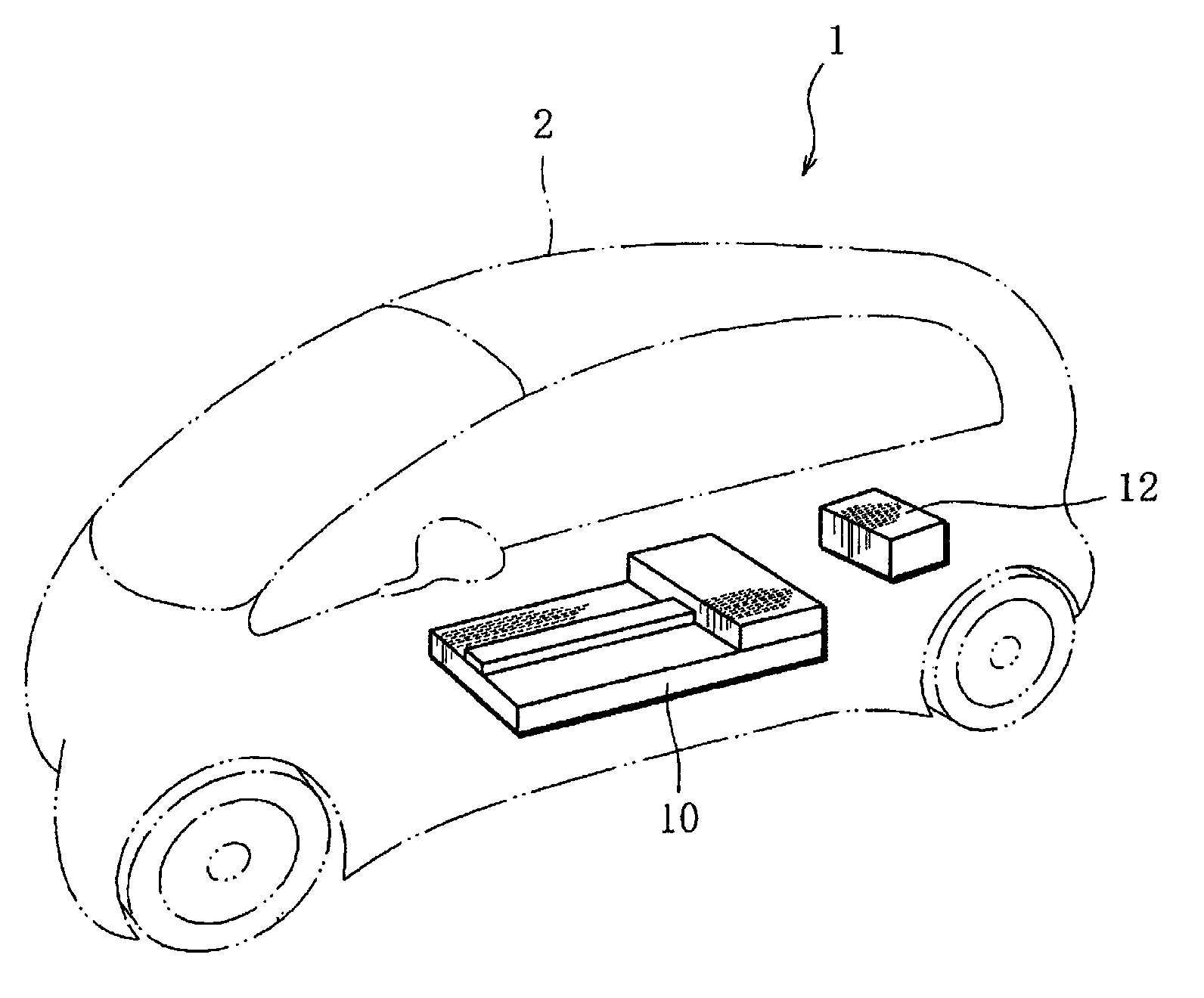
[0053] figure 1 It is a perspective view of an electric vehicle equipped with a battery case of the present invention.

[0054] Such as figure 1 As shown, the electric vehicle 1 has a battery case 10 placed under the floor of the vehicle body 2, and an external charging path (not shown), and a charger 12 for receiving power supply from the charging path and charging is arranged on the vehicle body. 2, the battery case 10 is connected to a charger 12 to store electricity.

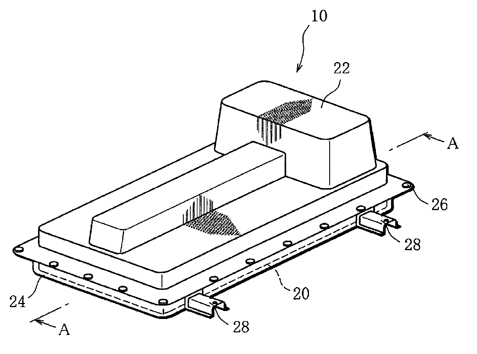
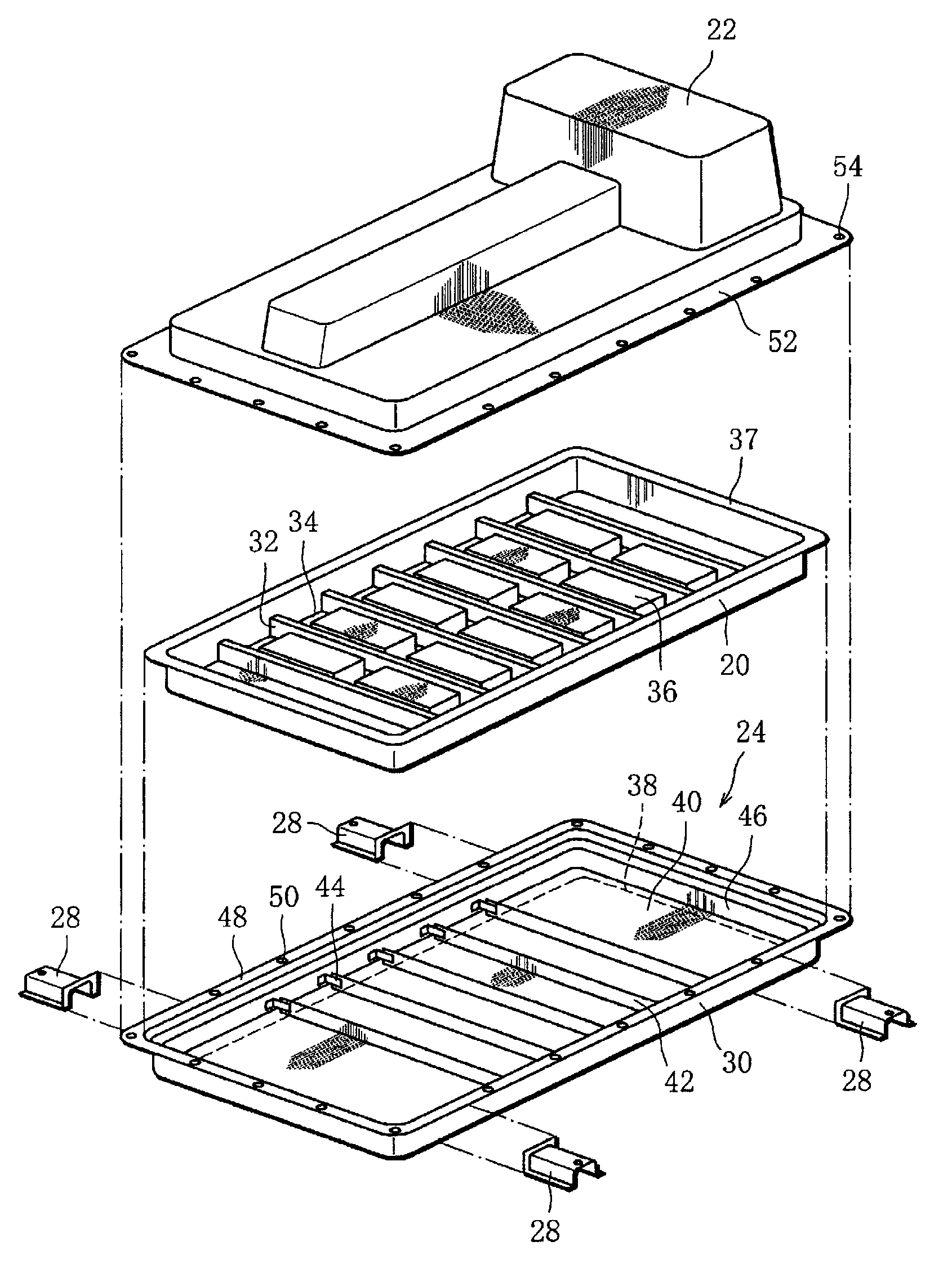
[0055] figure 2 A schematic configuration diagram of the battery case 10 is shown.

[0056] The battery case 10 includes: a resin tray (tray part) 20; a case (case part) 22; a frame (reinforcing tray part, frame part) 24 covering the outer periphery of the resin tray 20; and a mounting bracket 28 for mounting the battery case 10 on the vehicle body 2 .

[0057] The resin tray 20 and the case ...


PUM


Abstract

Disclosed is a battery case for a vehicle, which is provided with: a resin tray member (20), which holds a battery (36), and which has a plurality of protruding sections (32) formed on the bottom portion (34); and a reinforcing tray member, which is disposed on the outer surface of the tray member, and which has at least one reinforcing member (42), which is configured of a metal plate that is provided upright on the side that faces the tray member. On the outer surface of each of the protruding sections, a recessed section (56) is formed, corresponding to at least the reinforcing member, and the reinforcing member is fitted in the recessed section.

Description

technical field [0001] The present invention relates to a battery case for a vehicle, and more specifically, to a battery case for accommodating a battery for driving an electric vehicle. Background technique [0002] In recent years, hybrid vehicles and electric vehicles equipped with a large-capacity battery and using a driving motor driven by electric power of the battery as a power source have been widely developed. [0003] Such a battery case mounted on an electric vehicle includes, for example, a tray member for accommodating the battery, and a cover member for covering the tray member. [0004] Since a plurality of battery modules of the battery case of such a structure are arranged on the pallet member, when the battery case is mounted on the vehicle body, the pallet member exists due to the weight of the battery modules and the pallet member is mounted on the vehicle body. The lower surface of the frame member deflected, making it impossible to maintain the specif...

Claims


Application Information

Patent Timeline
Patent Type & Authority Applications(China)
IPC IPC(8): H01M2/10B60K1/04H01M50/204H01M50/224H01M50/227H01M50/229H01M50/244H01M50/249H01M50/278
CPCY02E60/12B60K1/04H01M2/1083Y02T90/124Y02E60/10H01M50/229H01M50/224H01M50/244H01M50/278B60L50/64H01M50/227H01M50/249H01M50/204H01M2220/20B60Y2200/91Y02T90/12
Inventor 卢颖樑藤原雄高吉冈秀记井上靖浩绪方文博高崎静一本城英喜
Owner MITSUBISHI MOTORS CORP
Why Eureka
Try Eureka