
Vehicular suspension arm

a technology for suspension arms and vehicles, applied in the direction of suspension arms with a strong grip, vehicle components, pivoted suspension arms, etc., can solve the problems of high cost, difficult to meet the recent demand for diversification, heavy weight, etc., and achieve the effect of simplifying the machining step, increasing strength, and increasing rigidity and strength

Inactive Publication Date: 2011-07-19
F TECH INC +1
View PDF23 Cites 19 Cited by
  • Summary
  • Abstract
  • Description
  • Claims
  • Application Information

AI Technical Summary

Benefits of technology

The present invention aims to provide a vehicular suspension arm that can solve the conventional problems of a plate type arm by means of a simple structure, even if the arm main body is made from a press-formed metal plate. The invention aims to address the need for a simpler and more cost-effective solution that can meet the strength requirements of different vehicle types without adding weight or space. Additionally, the invention aims to address the strength-related problems that might be difficult to deal with for a type of vehicle that has a particularly large fore-and-aft input load from the tire.

Problems solved by technology

However, when a suspension arm is produced by forging or casting as shown in, for example, FIG. 28(a) in order to meet all these requirements, there are problems such as heavy weight and high cost.
In order to solve these problems, an attempt has already been made to make a suspension arm by press-forming a metal plate, but such a suspension arm tends to have a large cross-sectional shape for an arm main body middle part, which serves as a damper support part, it becomes difficult to meet the recent demand for diversification in vehicle needs (for example, an increase in wheel diameter, an increase in engine output, an increase in the size of the drive shaft, etc.), and there are inconveniences such as the types of vehicle to which it is applied being greatly restricted.

Method used


Image

  • Vehicular suspension arm
  • Vehicular suspension arm
  • Vehicular suspension arm

Examples


embodiment 1

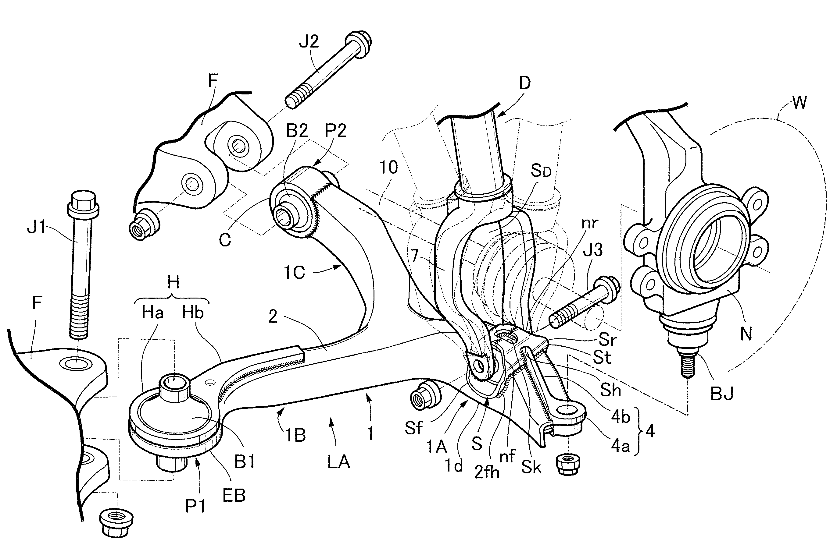
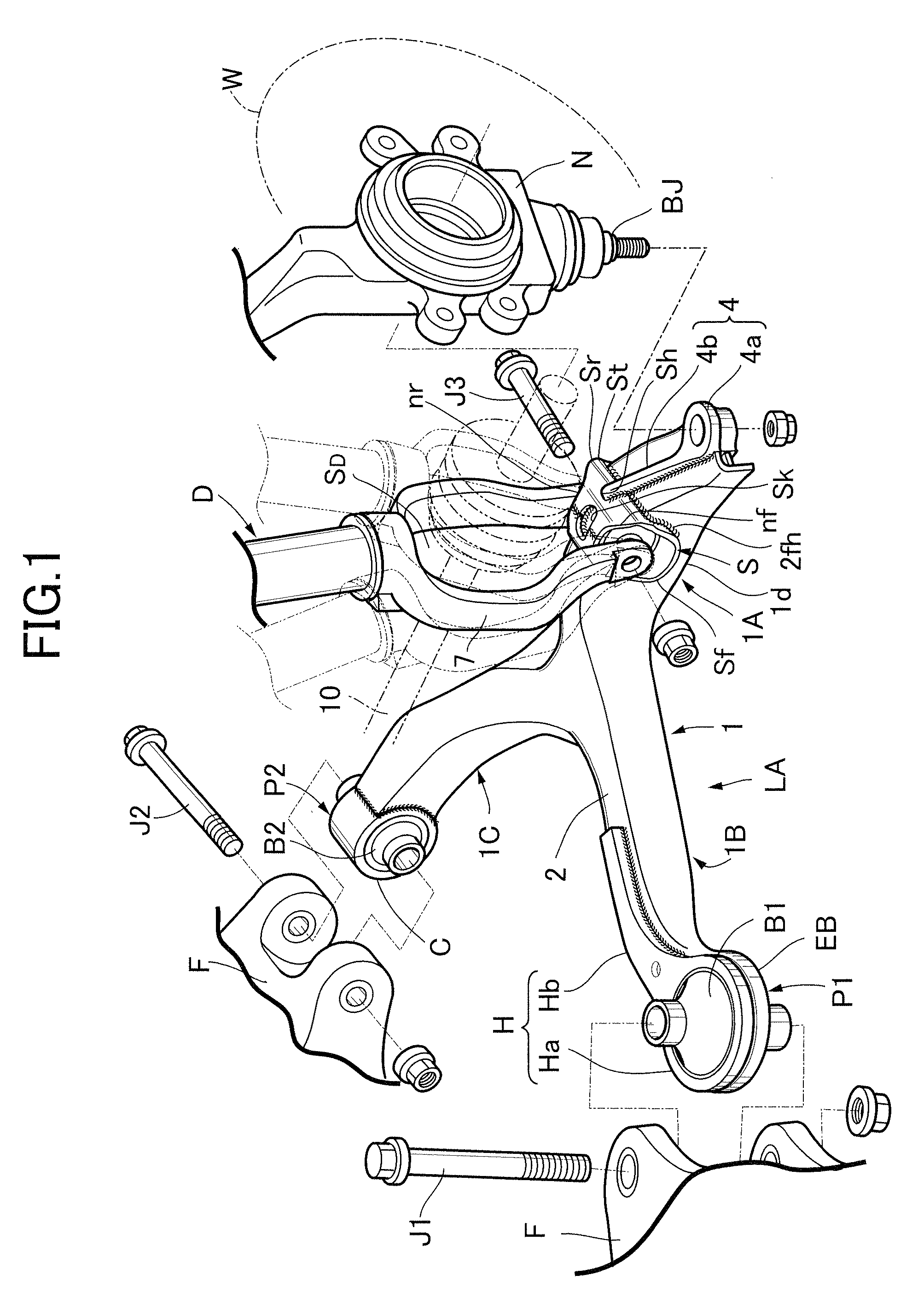
[0123]As shown in FIG. 1, a knuckle N rotatably supporting a wheel W has its lower part and its upper part vertically movably supported, on a vehicle body or a subframe connected thereto (hereinafter, simply called a vehicle body F), by a lower arm A and an upper arm (not illustrated) respectively. Furthermore, a damper D equipped with a coil spring is disposed between the vehicle body F and a middle part of the lower arm A in order to support the weight of the vehicle body and cushion vertical movement of the knuckle N.

[0124]The lower arm A is a so-called A type arm and forms a suspension arm of the present invention. This lower arm LA has its outer end part swivelably joined to the knuckle N via a ball joint BJ and has bifurcated first and second inner end parts joined to the vehicle body F via a pair of front and rear rubber bushes B1 and B2 and connecting pins J1 and J2 running therethrough.

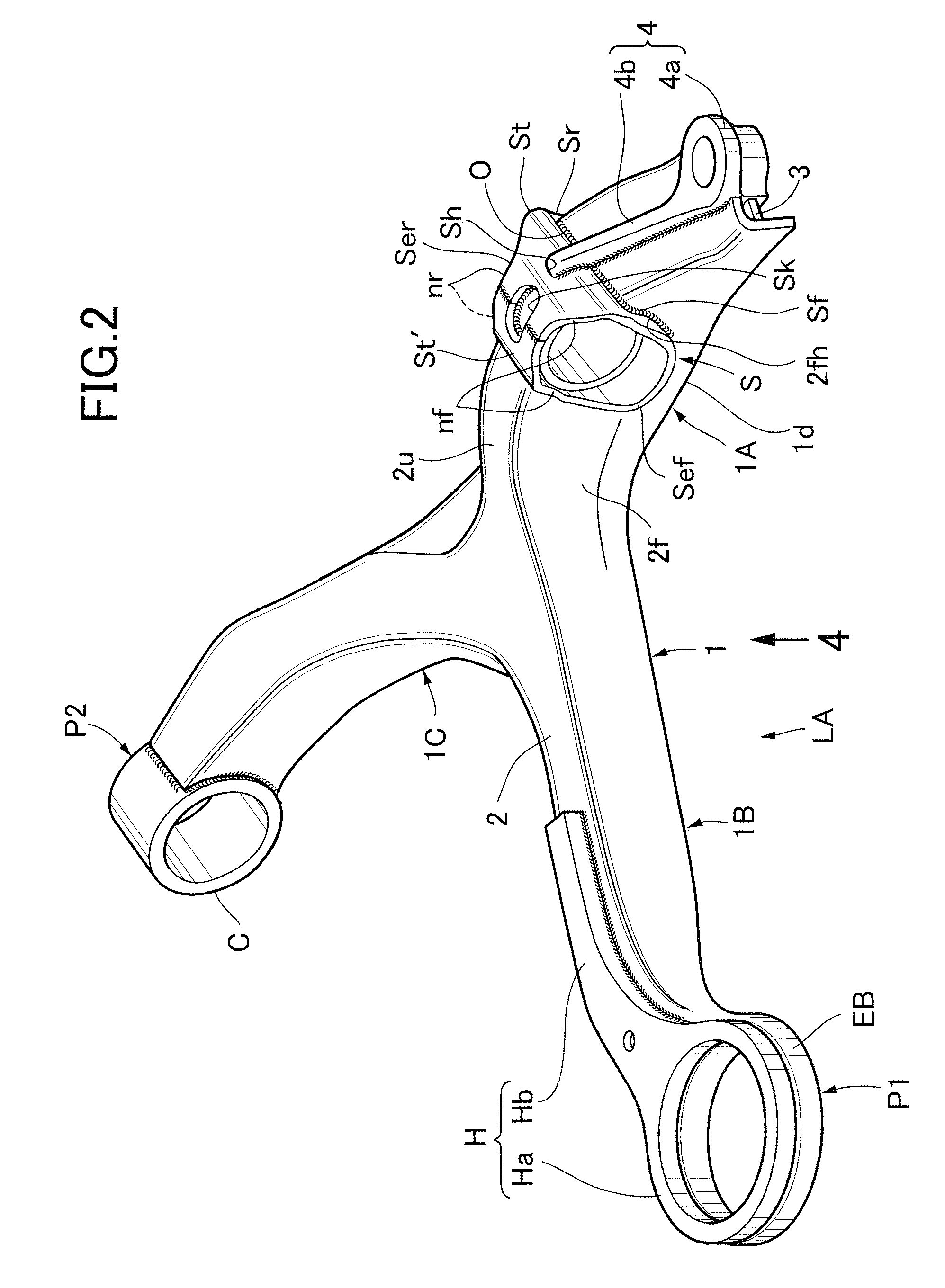
[0125]Referring to FIG. 2 to FIG. 5 together, an arm main body 1 of the lower arm LA is f...


PUM


Abstract

A vehicular suspension arm is provided in which an arm main body (1) includes a main plate (2) press-formed as a main part of the arm main body and having a short cylindrical part (EB) provided integrally with one end by flanging, and a reinforcing plate (H) superimposed on one of upper and lower faces of the main plate (2) and reinforcing the main plate (2). The reinforcing plate (H) has an eye-shaped head part (Ha) formed in an annular shape and arranged coaxially with the short cylindrical part (EB), and a tail part (Hb) extending integrally from the eye-shaped head part (Ha) along the longitudinal direction of the main plate (2), is formed from a single plate material that is thicker than the main plate (2), and has at least the tail part (Hb) welded to the main plate (2). A bush press-fit portion (P1) is formed from an inner peripheral face of the eye-shaped head part (Ha) and an inner peripheral face of the short cylindrical part (EB). This ensures that the cross-sectional shape of a transition section from the bush press-fit portion to the plate-type arm main body is adequate, thus enabling the rigidity and strength required for the transition section to be easily guaranteed and, furthermore, it becomes possible to meet a requirement for increasing the strength of the arm without specially increasing the space around the outer periphery of the bush press-fit portion.

Description

CROSS-REFERENCE TO RELATED APPLICATION[0001]This application is a National Stage entry of International Application No. PCT / JP2006 / 316095, filed Aug. 16, 2006, the entire specification claims and drawings of which are incorporated herewith by reference.TECHNICAL FIELD[0002]The present invention relates to a vehicular suspension arm having an arm main body formed from a metal plate.BACKGROUND ART[0003]With regard to a vehicular suspension arm that includes an arm main body made of a metal plate and a bush press-fit portion, provided at one end of the arm main body, into which a bush can be press-fitted, there has already been proposed, for example, an arrangement in which a pair of upper and lower inner peripheral flanges are formed by flanging inner peripheral parts of ring plate-shaped upper and lower end plates integrally connected respectively to one end of an upper plate and one end of a lower plate forming the arm main body so as to face each other inwardly, and inner periphera...

Claims


Application Information

Patent Timeline
Patent Type & Authority Patents(United States)
IPC IPC(8): B60G3/14
CPCB60G7/001B60G2200/144B60G2204/129B60G2204/1431B60G2206/014B60G2206/017B60G2206/122B60G2206/722B60G2206/8103B60G2206/8201
Inventor INOUE, MITSURUKIKUCHI, FUMIOHOZUMI, YUTAKAMATSUIKE, JUN
Owner F TECH INC
Learn More