Ratchet-type tensioner

A tensioner and ratchet-type technology, applied in the directions of machines/engines, belts/chains/gears, valve details, etc., can solve the problem of damage to the meshing teeth 536 and the rack 538, and the inability to completely and quickly release the meshing teeth 536 and the teeth Article 538. Problems that cannot be completely prevented, etc., to achieve the effect of simple production

Inactive Publication Date: 2010-11-24
TSUBAKIMOTO CHAIN CO
View PDF4 Cites 20 Cited by
  • Summary
  • Abstract
  • Description
  • Claims
  • Application Information

AI Technical Summary

Problems solved by technology

[0005] In the above-mentioned existing tensioner 500, such as Figure 7 As shown, the oil chamber 516 that acts on the oil pressure of the plunger 514 and the auxiliary oil chamber 520 that acts on the oil pressure on the piston 526 are respectively connected to the oil passage 548 and the oil passage 544 branched from the same oil tank 550. When the air enters the auxiliary oil chamber 520, it is affected by the external oil pressure pulsation generated from the oil pump when the engine is started, so that sufficient oil pressure cannot be ensured for the auxiliary oil chamber 520, causing the piston 526 to move based on the oil pressure of the auxiliary oil chamber 520. The backward movement of the rack is unstable, so that the engagement between the engaging teeth 536 and the rack 538 cannot be released completely and quickly, and the engagement between the engaging teeth 536 and the rack 538 may be damaged.
[0006] Therefore, the deficiency of the existing tensioner 500 is that the engagement between the engaging teeth 536 and the rack 538 cannot be completely and quickly released when the engine is started, and the forward and backward movement based on the smooth sliding of the plunger 514 cannot be realized after the engine is started, and Due to the incomplete meshing of the meshing teeth 536 and the rack 538, the meshing teeth 536 and the rack 538 will be damaged, so that the force of the plunger 514 corresponding to the wear and elongation of the timing chain cannot be ensured, and the plunger 514 cannot be completely stopped. The plug 514 receives a phenomenon called back lash from the timing chain and cannot eliminate noise such as abnormal sound caused by the vibration of the timing chain. The spring 518 must be made of high-strength material capable of withstanding the backlash of the plunger 514, resulting in the enlargement of the tensioner itself

Method used


Image

  • Ratchet-type tensioner
  • Ratchet-type tensioner
  • Ratchet-type tensioner

Examples


Embodiment

[0033] Refer to the following Figure 1 to Figure 6 A ratchet type tensioner 100 which is an embodiment of the present invention will be described.

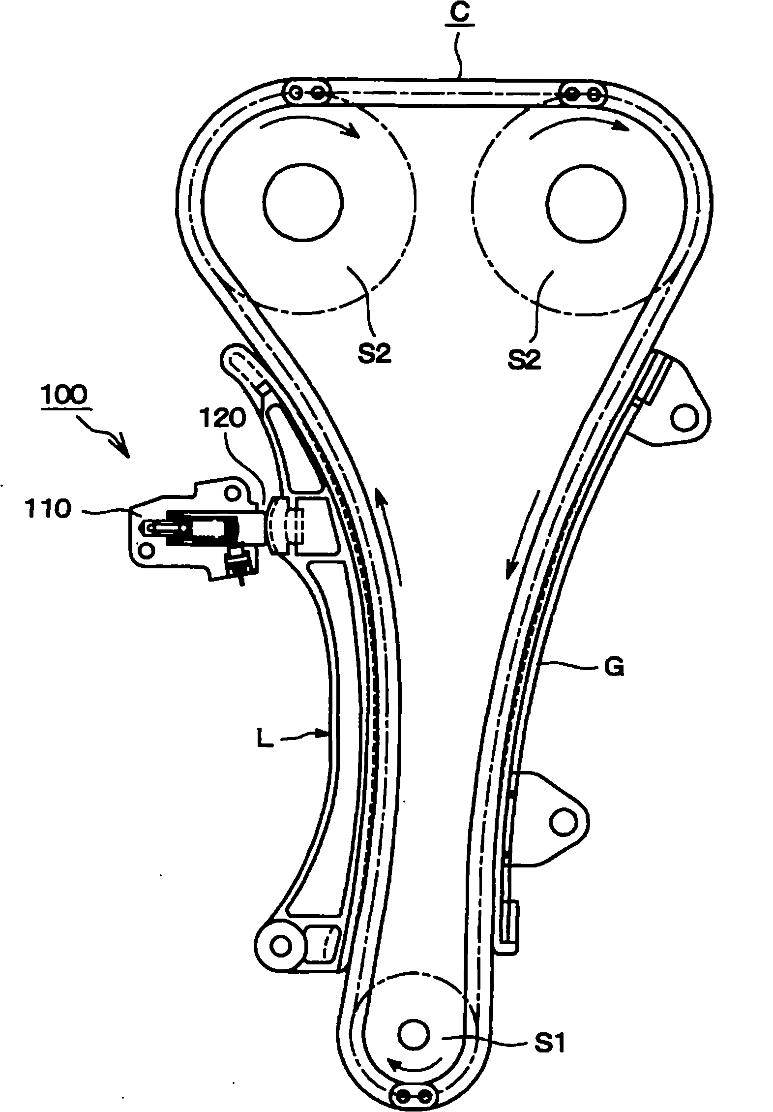
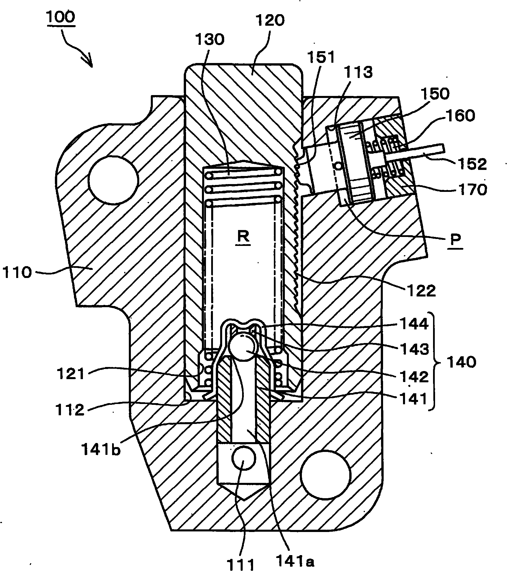
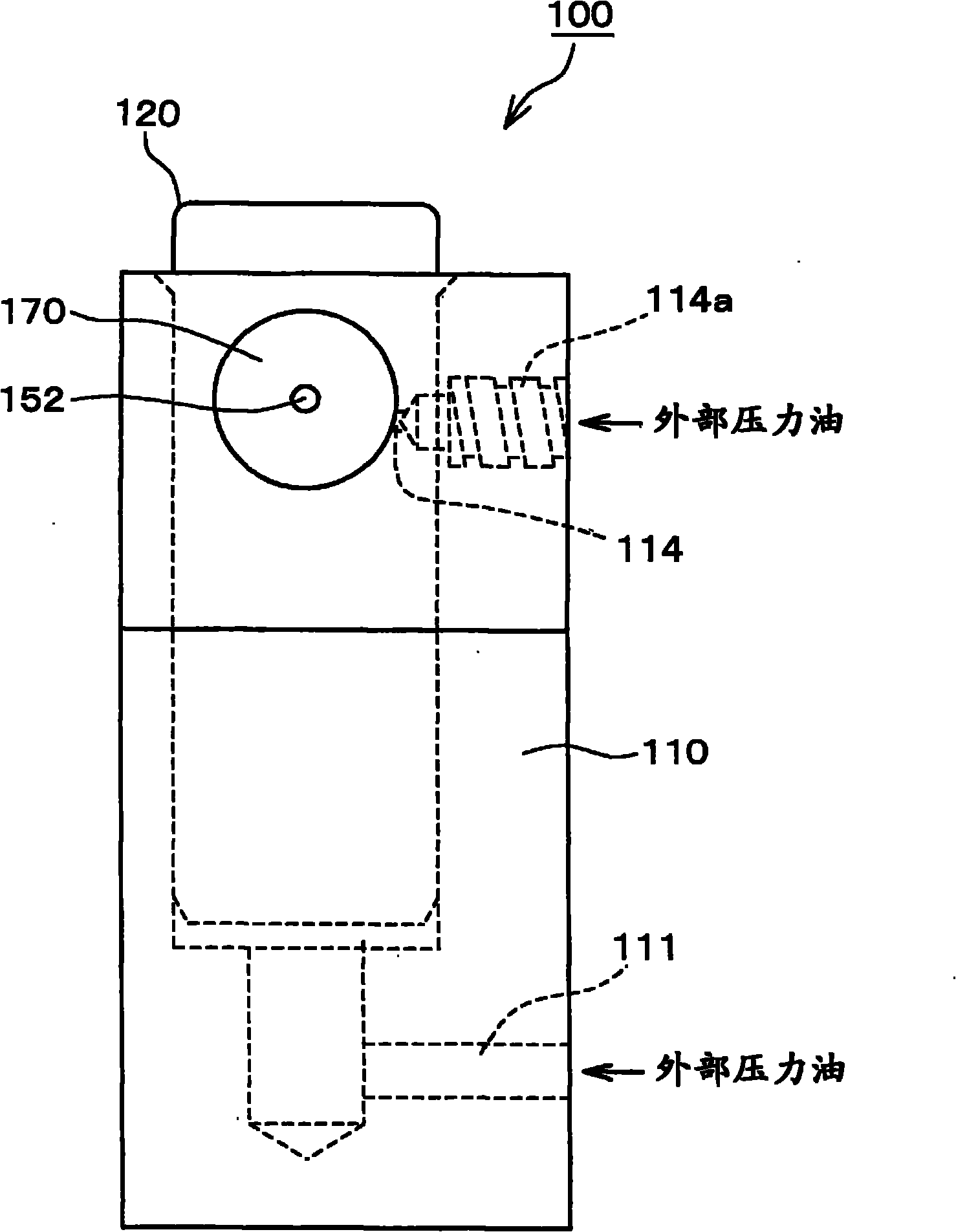
[0034] here, figure 1 It is a use state diagram of the ratchet tensioner 100 according to the first embodiment of the present invention. figure 2 for figure 1 An enlarged cross-sectional view of ratchet tensioner 100 is shown, image 3 its side view. Figure 4 It is a cross-sectional view showing the meshing state of the rack teeth of the plunger and the ratchet pawl of the piston with ratchet. Figure 5 It is a cross-sectional view showing the meshing release state of the rack teeth of the plunger and the ratchet pawl of the piston with ratchet.

[0035] First, if figure 1 As shown, the ratchet type tensioner 100 according to the first embodiment of the present invention is of the timing chain C wound between the driving side sprocket S1 rotated by the crankshaft of the engine and the driven side sprocket S2 fixed to t...


PUM


Abstract

The present invention provides a ratchet-type tensioner (100) which prevents a back clearance of a plunger piston from a timing chain when an engine after the engine after long-time placement, stably generates the oil pressure in a high-pressure oil chamber of a piston part that allows the retreating movement of piston, and smoothly realizes quick retreating movement of the plunger. A piston high pressure oil chamber (P) is provided between a piton accommodating hole (113) and a piston (150) with a ratchet, and is used for causing the ratchet teeth (151) of the piston (150) with ratchet to overcome the acting force of a plunger-biasing spring (160) and displace in a direction of releasing from a toothed rack (122) at the side surface of plunger. A second oil supply passage (114) which introduces the pressure oil into the piston high pressure oil chamber (P) is not branched from a first oil supply passage (111) for introducing the outside pressure chamber and is formed independently from a tensioner housing (110).

Description

technical field [0001] The present invention relates to a ratchet type tensioner that provides tension to a timing chain that drives a camshaft or the like of an engine. Background technique [0002] Conventionally, there is known a tensioner, which is used to drive a timing chain such as a camshaft of an engine, and uses a protruding force based on a spring and external oil pressure toward a column that is slidably inserted into a housing to form an oil chamber between it and the housing. The plug acts to provide tension to the timing chain. [0003] As such existing tensioners such as Figure 7 As shown, the tensioner 500 has: a piston 526, which is slidably inserted in the housing 512 in a direction perpendicular to the sliding direction of the plunger 514 and forms an auxiliary oil chamber 520 between it and the housing 512; The external oil pressure acts on the oil passage 544 of the auxiliary oil chamber 520; the air chamber 528 is equipped with a second spring 534 th...

Claims


Application Information

Patent Timeline
Patent Type & Authority Applications(China)
IPC IPC(8): F16H7/08F01L1/348
CPCF01L1/022F16H2007/0859F16H7/0848F16H2007/0812F16H2007/0853F01L1/02F16H2007/0806
Inventor 平山学松下尊弘中久保克也榑松勇二吉田修吉本慎太郎
Owner TSUBAKIMOTO CHAIN CO
Why Eureka
Try Eureka