Engagement chain type driving device

A driving device and meshing technology, which is applied to portable lifting devices, hoisting devices, hoisting devices, etc., can solve the problems of damage to the design freedom of the device, reduced bending strength, and complexity, so as to ensure rigidity, stable forward and backward drive, and improve bending intensity effect

Active Publication Date: 2010-03-17
TSUBAKIMOTO CHAIN CO
View PDF1 Cites 11 Cited by
  • Summary
  • Abstract
  • Description
  • Claims
  • Application Information

AI Technical Summary

Problems solved by technology

[0005] However, in the conventional drive device, due to the above-mentioned gaps between the bending restriction flat surfaces 555a, each link piece 555 is loosened, or a bending restriction occurs between the opposing link pieces 555. The relative offset of the flat surface 555a cannot ensure the rigidity of the pair of meshing chains 550 that are meshed with each other. Therefore, it is necessary to provide an auxiliary guide mechanism 590 that prevents the pair of meshing chains 550 from bending and tilting to guide the stable lifting drive of the load supporting member 510, such as like Figure 12 As shown, an auxiliary guide mechanism 590 composed of a telescopic mechanism is provided between the load supporting member 510 and the installation ground side, and the installation of the auxiliary guide mechanism 590 complicates the entire device, thereby impairing the degree of freedom in device design. The problem
[0006] In addition, regarding the above-mentioned problem that the bending strength of the pair of engaging chains 550 decreases due to the gap between the bending limiting flat surfaces 555a, as described in Japanese Patent No. 3370928, the ground is installed as the installation surface. In the case of using the engaging chain 550 with the driving device installed, the effect can be reduced by eliminating the gap generated between the bending limiting flat surfaces 555a due to the weight of the load supporting member 510 and the workpiece acting on the pair of engaging chains 550. However, when the engaging chain 550 is used for a drive device in the form of a suspension installation installed on the ceiling surface or a drive device in the form of cantilever support installed on a vertical wall surface, the above-mentioned problems will become apparent.

Method used


Image

  • Engagement chain type driving device
  • Engagement chain type driving device
  • Engagement chain type driving device

Examples


Embodiment Construction

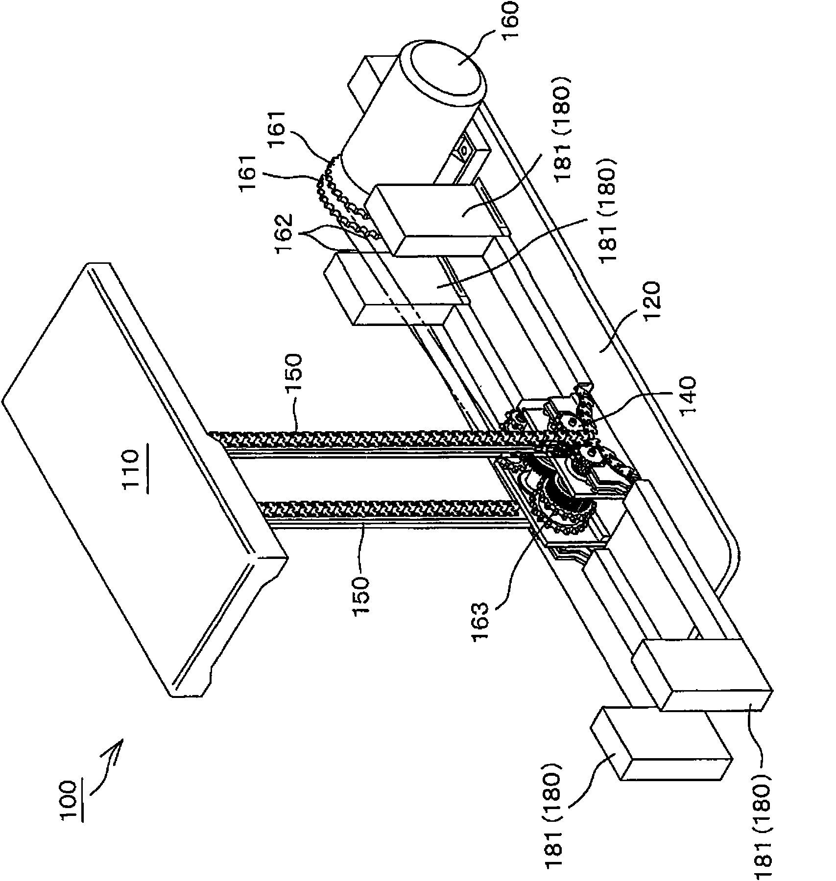
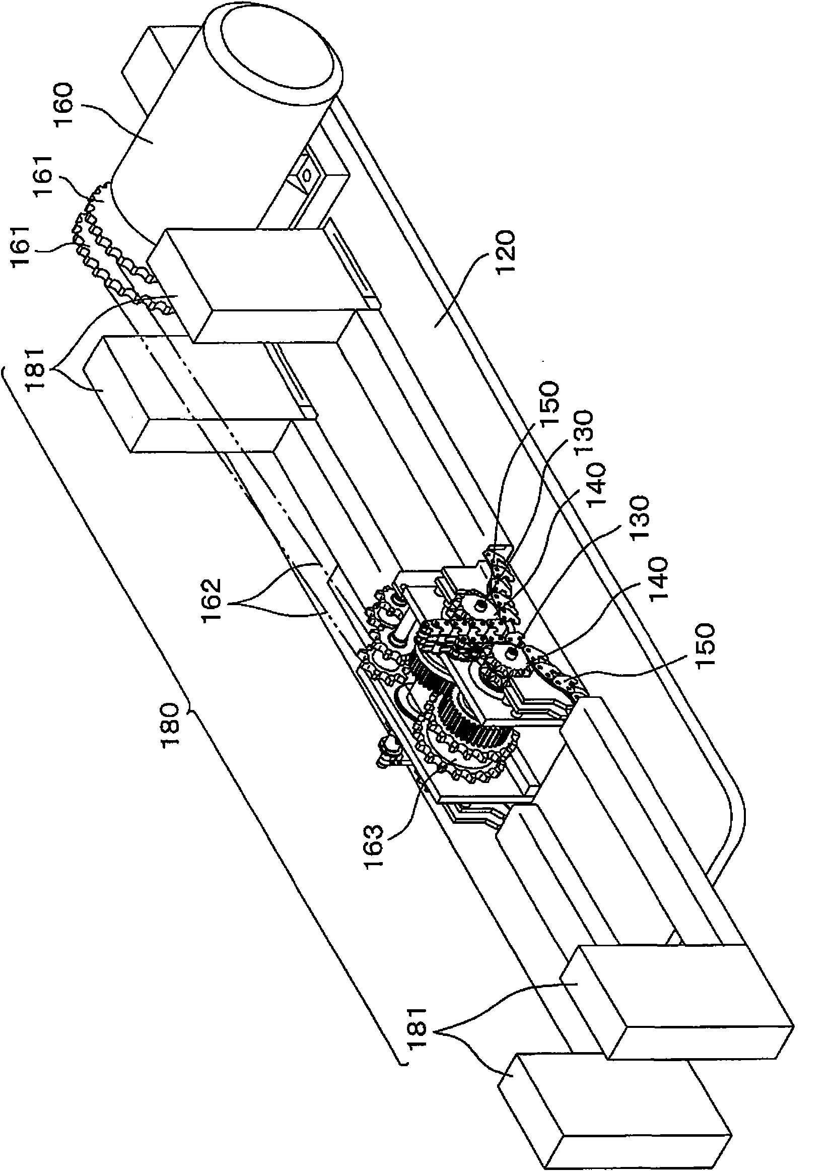
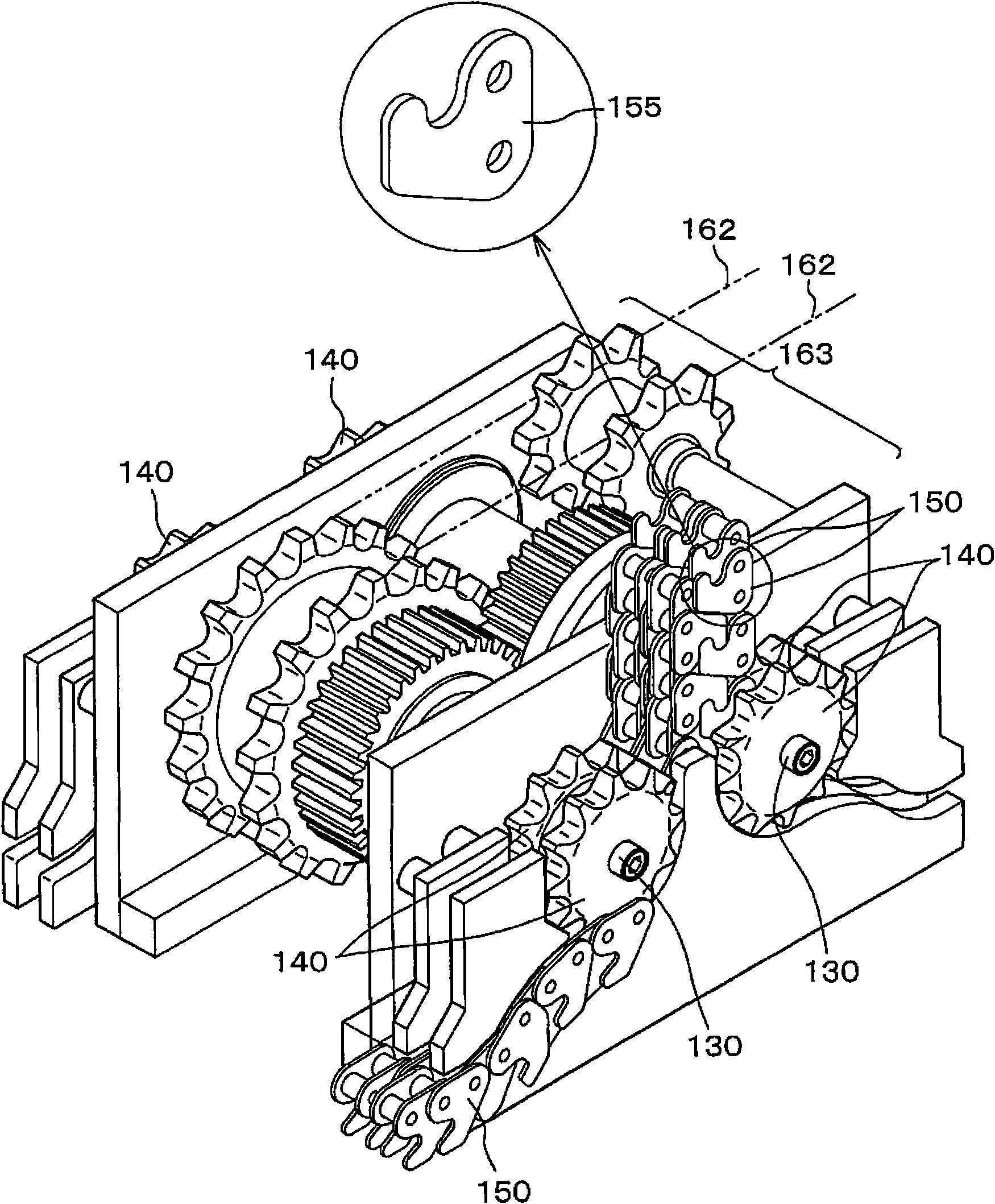
[0034] The meshing chain type lifting device of the present invention can be implemented in any way as long as it is the following device. Opposite each other in the same plane, and rotate forward and reverse in opposite directions; a pair of meshing chains, on the one hand, are integrated through a pair of driving sprockets, and on the other hand, are mutually meshed and disengaged through a pair of driving sprockets And separate; and the drive source, which drives a pair of drive sprockets, respectively forming a curved limiting flat surface to maintain the meshing posture of the chain on the inner tooth piece and the outer tooth piece constituting the meshing chain, and meshing into one by using the driving sprocket In the state where the inner tooth pieces and the outer tooth pieces face each other, the above-mentioned bending restricting flat surfaces come into surface contact with each other, thereby realizing stable forward and backward driving of the workpiece without p...


PUM


Abstract

The invention provides an engagement chain type driving device which can realize the advance and retreat drive without the auxiliary guide mechanism, and can realize the reduction in size and light, and ensure the high free degree for the design of other parts, the arrangement position of the devices, and the like, and can make the maintenance easy and reduce the coveying load of the workpieces, at the same time, when the suepension or suspension arm supporting is adopted, the auxiliary guide mechanism is also not required. The invention relates to an engagement chain type driving device including a pair of driving sprockets, a pair of engagement chains, and a driving source, wherein the inner tooth plates and outer tooth plates being brought opposite to each other and into contact with each other when the engagement chains are integrated by the pair of driving sprockets, such that the flat surfaces hold the chain engagement position.

Description

technical field [0001] The present invention relates to a driving device used in manufacturing equipment in various manufacturing fields, conveying equipment in the transportation field, nursing equipment in the medical and welfare field, stage equipment in the art field, etc. The chain is an intermeshing chain drive device that serves as the drive medium for the forward and backward motion. Background technique [0002] Conventionally, as a drive device, there is a drive device that uses a pair of meshing chains that engage with each other to move up and down integrally, so-called chuck chains, to move a workpiece such as a heavy object up and down (for example, refer to Patent Document 1). [0003] In the meshing chain 550 used in this conventional driving device, various studies have been carried out on the shape of the hook surface 555b formed on each link piece 555, the distance between the pins and the distance between the bushes, and the like. The area on the opposit...

Claims


Application Information

Patent Timeline
Patent Type & Authority Applications(China)
IPC IPC(8): B66F3/02
CPCB66D3/20B66F3/06F16G13/20B66F3/08B66F7/14
Inventor 须子友男中西耕平佐治智之竹内佳史上田敬柴田直人
Owner TSUBAKIMOTO CHAIN CO
Why Eureka
Try Eureka