Power hub

A wheel hub and yoke technology, applied in the field of power generation hubs, can solve problems such as easy deformation, adjustment, and hindering the positioning of yoke claws, and achieve the effects of high structural strength, flexible structural changes, and easy winding work

Inactive Publication Date: 2012-02-22
廖 贵堂 +1
View PDF6 Cites 0 Cited by
  • Summary
  • Abstract
  • Description
  • Claims
  • Application Information

AI Technical Summary

Problems solved by technology

[0002] U.S. Patent No. 7002880 and Chinese Taiwan Patent Application No. 92107400 and No. 94215996 disclose a generator hub, a bobbin used is used to provide a coil winding, and to provide the insertion of a plurality of yoke claws Positioning is used so that there are multiple slots distributed around the periphery of the bobbin. When manufacturing, the first disadvantage is that the groove-like structure around the bobbin is adjacent to the winding area, because it is easy to hook the thread. Therefore, it will hinder the winding work. The second disadvantage is that the winding frame is usually made of plastic material, which is easily deformed after winding and hinders the positioning of the yoke claws. The third disadvantage is that the slot on the winding frame determines the The number of poles of the power generation hub, because the slots have been fixed and formed on the winding frame, so the number of poles cannot be adjusted to meet different power generation requirements, and the mold must be re-manufactured, thus increasing the cost

Method used


Image

  • Power hub
  • Power hub
  • Power hub

Examples


Embodiment Construction

[0011] Below in conjunction with accompanying drawing and embodiment the present invention is described in detail:

[0012] Before the present invention is described in detail, it should be noted that in the following description, similar elements are denoted by the same reference numerals.

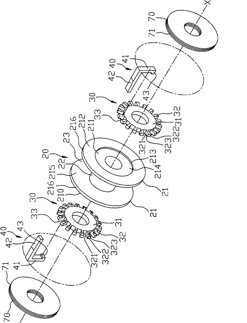
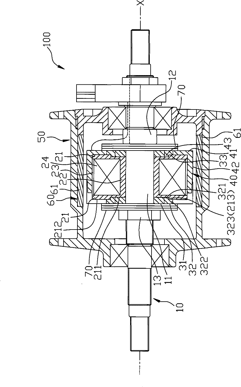
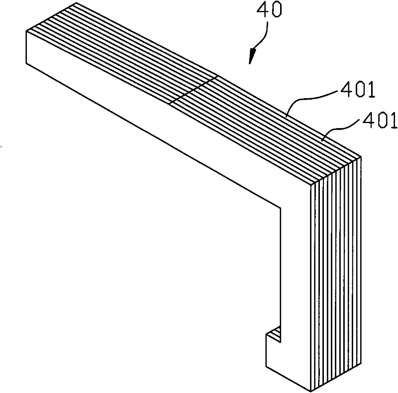
[0013] like figure 1 , 2 As shown, the first preferred embodiment of the generator hub 100 of the present invention includes a mandrel 10, a bobbin 20, two yoke disks 30, a plurality of yoke claws 40, a housing 50, a magnetic unit 60 and Two sets of isolation shutter sets 70.

[0014] The mandrel 10 extends along an axis X and includes a mounting section 11 , a retaining ring 12 located at a front side of the mounting section 11 , and a nut 13 screwed to a rear side of the mounting section 11 .

[0015] The bobbin 20 is fixed on the mounting section 11, and includes two side walls 21 spaced around the axis X, a cylinder wall 22 connected between the side walls 21 along the axis X, a A...


PUM


Abstract

A generator wheel hub includes a mandrel, a winding frame, two yoke discs, a plurality of yoke claws, a shell and a magnetic force unit. The winding frame is magnetically permeable and includes two side walls, a cylinder wall connected between the side walls, a winding slot between the side walls and the cylinder wall, and a coil wound on the The winding slot for the coil. Each of the yoke plates includes a plurality of radially extending protrusions, and a plurality of pole peg grooves formed between the protrusions, the yoke plates are respectively connected to the side walls and the magnets The pole peg slots of the yoke disc are staggered with each other. The yoke claws are respectively inserted in the pole bolt slots, and each includes an axial section extending to the outside of the winding slot. The magnetic force unit is arranged on the inner peripheral surface of the housing and has a plurality of magnets corresponding to the yoke claws.

Description

technical field [0001] The invention relates to a wheel hub for bicycles, in particular to a generator hub. Background technique [0002] U.S. Patent No. 7002880 and Chinese Taiwan Patent Application No. 92107400 and No. 94215996 disclose a generator hub, a bobbin used is used to provide a coil winding, and to provide the insertion of a plurality of yoke claws Positioning is used so that there are multiple slots distributed around the periphery of the bobbin. When manufacturing, the first disadvantage is that the groove-like structure around the bobbin is adjacent to the winding area, because it is easy to hook the thread. Therefore, it will hinder the winding work. The second disadvantage is that the winding frame is usually made of plastic material, which is easily deformed after winding and hinders the positioning of the yoke claws. The third disadvantage is that the slot on the winding frame determines the As for the number of poles of the power generation hub, since th...

Claims


Application Information

Patent Timeline
Patent Type & Authority Patents(China)
IPC IPC(8): H02K21/12B62J6/12
Inventor 廖贵堂陈浚钦
Owner 廖 贵堂
Why Eureka
Try Eureka