Aluminum alloy heat exchanger and method for producing the same
一种热交换器、散热片的技术,应用在热交换器固定、热交换设备、制造工具等方向,能够解决热交换性能降低、不能实现热交换器充分的功能等问题,达到防止优先腐蚀、抑制优先腐蚀、防止脱落的效果
- Summary
- Abstract
- Description
- Claims
- Application Information
AI Technical Summary
Problems solved by technology
Method used
Image
Examples
Embodiment
[0146] Al alloys for tubes with the composition shown in Table 1 and Al alloys for heat sinks with the composition shown in Table 2 were melted. In addition, Al alloys for the core material, Al alloys for the sacrificial material layer, and Al alloys for the brazing material layer having the compositions shown in Table 3 were melted.
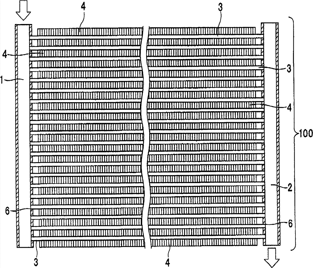
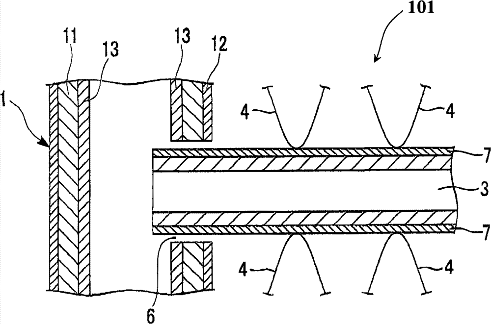
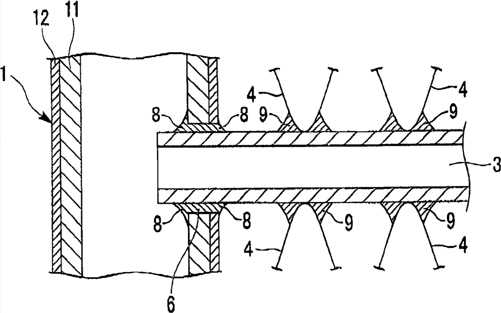
[0147] After the tube is homogeneously heat-treated with an Al alloy, it is prepared by hot extrusion Figure 4 , Figure 6A The cross-sectional shape shown (wall thickness 0.30mm×width 18.0mm×overall thickness 1.5mm: side flat surface height 0.6mm, corner R: 0.45mm), (side flat surface height 0.9mm, corner part R: flat tube 3 of 0.3 mm). Additionally, prepare Figure 6B and Figure 7B The side S shown is a pipe 31 in an arc shape (arc radius: 0.75mm, 1.5mm), Figure 6C The sides shown are beveled (90° included angle) tubes.
[0148] After the Al alloy for heat sinks was homogeneously heat-treated, hot rolling and cold rolling were perform...
Embodiment 2
[0177] Except that the composition of the aluminum alloy for tubes was set to the composition shown in Table 5, a heat exchanger 100 was produced in the same manner as in Example 1, and the depth of corrosion on the tube 3 and the residual rate of the fins 4 were measured. The results are shown in Table 5. In addition, No. 4 in Table 4 was used as the brazing composition coated on the pipe 3 .
[0178] table 5
[0179] Tube
[0180] As shown in Table 5, the corrosion resistance of the tube 3 and the residual ratio of the fins 4 changed depending on the Mn content and the Si content of the tube 3 . For this reason, the preferred ranges of the present invention are set as follows: Mn is 0.15-0.45%, and Si is 0.20-0.50%.
Embodiment 3
[0182] Except that the composition of the aluminum alloy for fins was set to the composition shown in Table 6, a heat exchanger 100 was prepared in the same manner as in Example 1, and the depth of corrosion on the tube 3 and the residual rate of the fins 4 were measured. The results are shown in Table 6. In addition, No. 4 in Table 4 was used as the brazing composition coated on the pipe 3 .
[0183] Table 6
[0184] cooling
[0185] As shown in Table 6, the corrosion resistance of the tube 3 and the residual ratio of the fins 4 vary depending on the constituent element contents of the alloy constituting the fins 4 . For this reason, in order to obtain a high heat sink bonding rate and excellent corrosion resistance, the following ranges are required: Zn: 1.20-1.80%, Si: 0.70-1.20%, Fe: 0.30-0.80%, and Mn: 0.90-1.50%. In addition, regarding Zr, V, and Cr, it is also known that the preferred ranges in the present invention are Zr: 0.05-0.20%, V: 0.01-0.10%, and Cr:...
PUM
| Property | Measurement | Unit |
|---|---|---|
| coating mass | aaaaa | aaaaa |
| coating mass | aaaaa | aaaaa |
| particle diameter | aaaaa | aaaaa |
Abstract
Description
Claims
Application Information
 - R&D
- Intellectual Property
- Life Sciences
- Materials
- Tech Scout
- Unparalleled Data Quality
- Higher Quality Content
- 60% Fewer Hallucinations
Browse by: Latest US Patents, China's latest patents, Technical Efficacy Thesaurus, Application Domain, Technology Topic, Popular Technical Reports.
© 2025 PatSnap. All rights reserved.Legal|Privacy policy|Modern Slavery Act Transparency Statement|Sitemap|About US| Contact US: help@patsnap.com


