
Vibrator

A vibrator and permanent magnet technology, applied in the direction of electrical components, electromechanical devices, etc., can solve the problems of obstruction and unsatisfactory vibration effect, and achieve the effect of long service life, good vibration effect and sensitive vibration

Inactive Publication Date: 2010-03-24
夏怀远
View PDF0 Cites 2 Cited by
  • Summary
  • Abstract
  • Description
  • Claims
  • Application Information

AI Technical Summary

Problems solved by technology

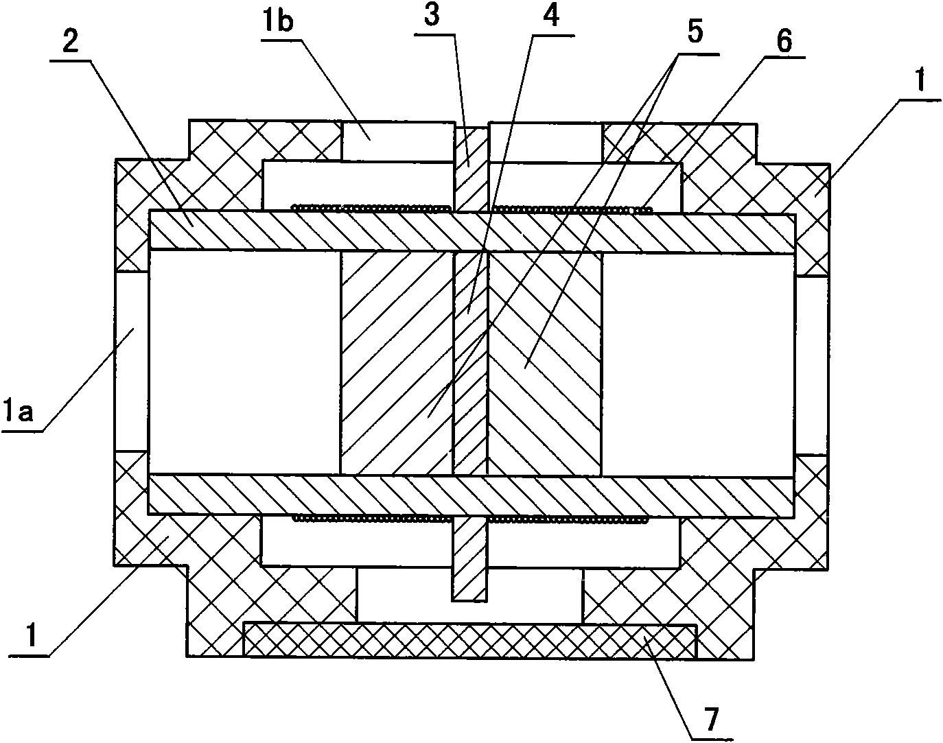
The disadvantages of the above existing electromagnetic vibrator are: the positioning of the vibrating element is realized by the contact with the spring, the amplitude of the vibrating element will be affected by the spring, and the vibration effect is not ideal; especially when the current passing through the coil is relatively low. Hours, the resistance of the spring will hinder the vibrating part more obviously

Method used


Image

  • Vibrator
  • Vibrator
  • Vibrator

Examples


Embodiment Construction

[0011] The present invention is further described below in conjunction with embodiment and accompanying drawing.

[0012] see figure 1

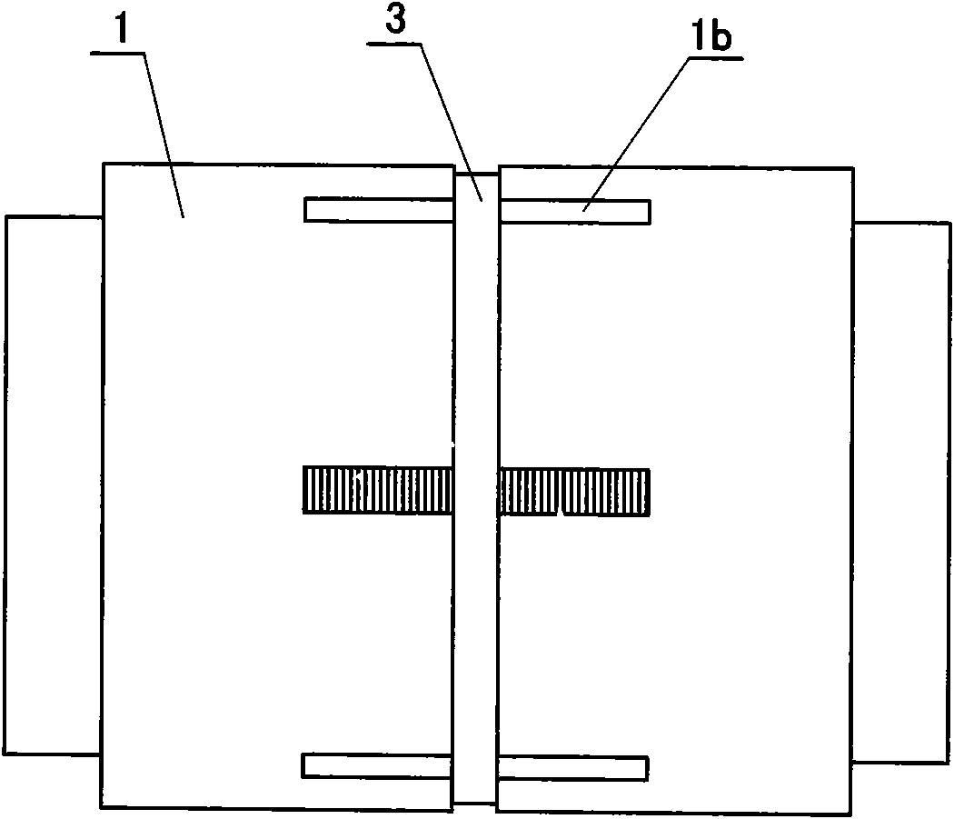
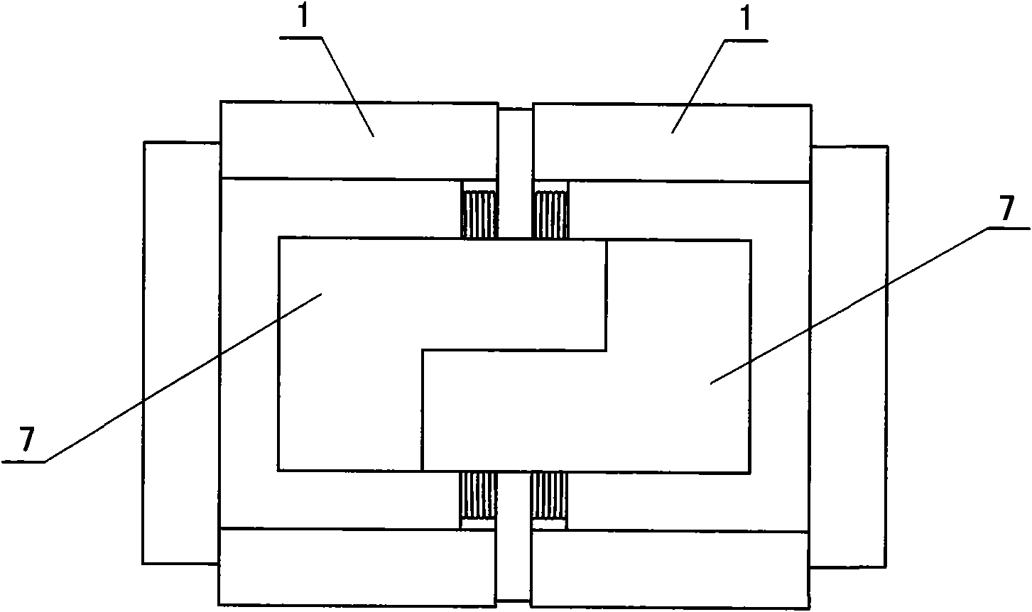
[0013] The vibrator provided by the present invention includes a permanent magnet 5, a coil 6 and a hollow cylinder 2, the permanent magnets 5 are a pair, and the two permanent magnets 5 are respectively fixed on both sides of a magnetic conducting ring 4 by bonding , and the ends with the same polarity of the two permanent magnets 5 face each other, the two permanent magnets 5 and the magnetic conducting sheet 4 are located in the cavity of the cylinder 2, and the vibrating element formed by the two permanent magnets 5 and the magnetic conducting sheet 4 is connected to the cylinder 2 Cavity clearance fit. A magnetic conduction ring 3 is sheathed in the middle of the surface of the cylinder 2 , the coil 6 is divided into two parts and wound on the surface of the cylinder 2 on both sides of the magnetic conduction ring 3 , and there are two...


PUM


Abstract

The invention relates to a vibrator which comprises permanent magnets, a coil and a hollow cylinder body, wherein, the permanent magnets are one pair, the two permanent magnets are respectively fixedon two sides of a magnetic conductive sheet, the ends with the same polarity of the two permanent magnets are opposite, the two permanent magnets and the magnetic conductive sheet are positioned in acavity of the cylinder body, a magnetic conductive ring is sheathed at the middle part of the surface of the cylinder body, the coil is divided into two parts and wound on the surface of the cylinderbody which is positioned on two sides of the magnetic conductive ring, a housing is sheathed outside the cylinder body, and two ends of the coil are introduced out of the housing. The vibrator has theadvantages of reasonable structure, sensitive vibration, good vibration effect and long service life, and can be widely applied on products like massage devices, sex toys, mobile phones and the like.

Description

technical field [0001] The invention relates to a vibrator, in particular to an electromagnetic vibrator. Background technique [0002] The basic structure of an existing electromagnetic vibrator is that a vibrating element with a magnet is arranged in a cavity of a hollow part, and a spring is placed between one or both ends of the vibrating element and the hollow part. A coil is wound on the outside. When the coil of this kind of electromagnetic vibrator passes through the alternating current, the vibrating part with the magnet can generate vibration. The disadvantages of the above existing electromagnetic vibrator are: the positioning of the vibrating element is realized by the contact with the spring, the amplitude of the vibrating element will be affected by the spring, and the vibration effect is not ideal; especially when the current passing through the coil is relatively low. When the time is small, the resistance of the spring will hinder the vibrating member more...

Claims


Application Information

Patent Timeline
IPC IPC(8): H02K33/18
Inventor 夏怀远
Owner 夏怀远
Learn More