Communication system using network base ip mobility protocol, control device, router, and communication method thereof
A technology for controlling equipment and communication systems, applied in the field of communication, which can solve problems such as the impossibility of maintaining a session
- Summary
- Abstract
- Description
- Claims
- Application Information
AI Technical Summary
Problems solved by technology
Method used
Image
Examples
no. 1 example
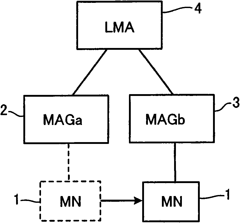
[0127] figure 1 is a diagram showing a schematic configuration of a network in this embodiment.
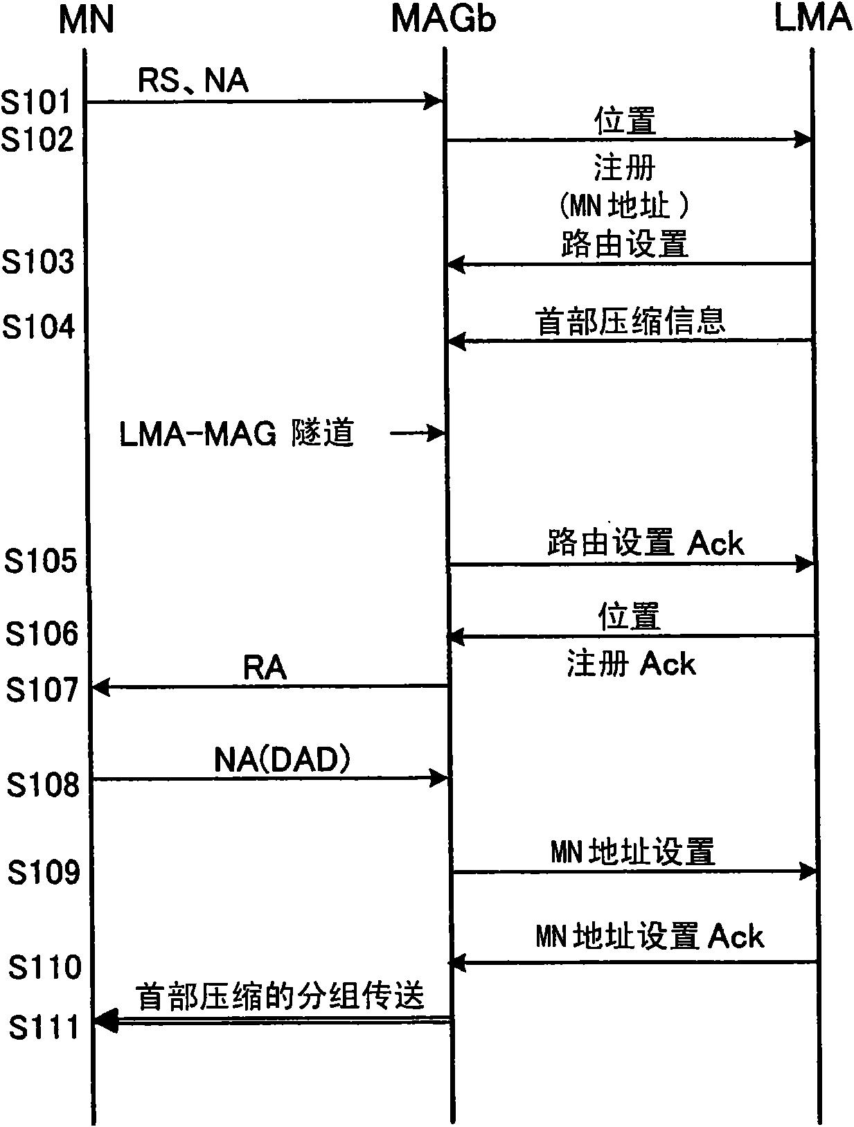
[0128] figure 2 is a sequence diagram showing procedural steps of processing in this embodiment.
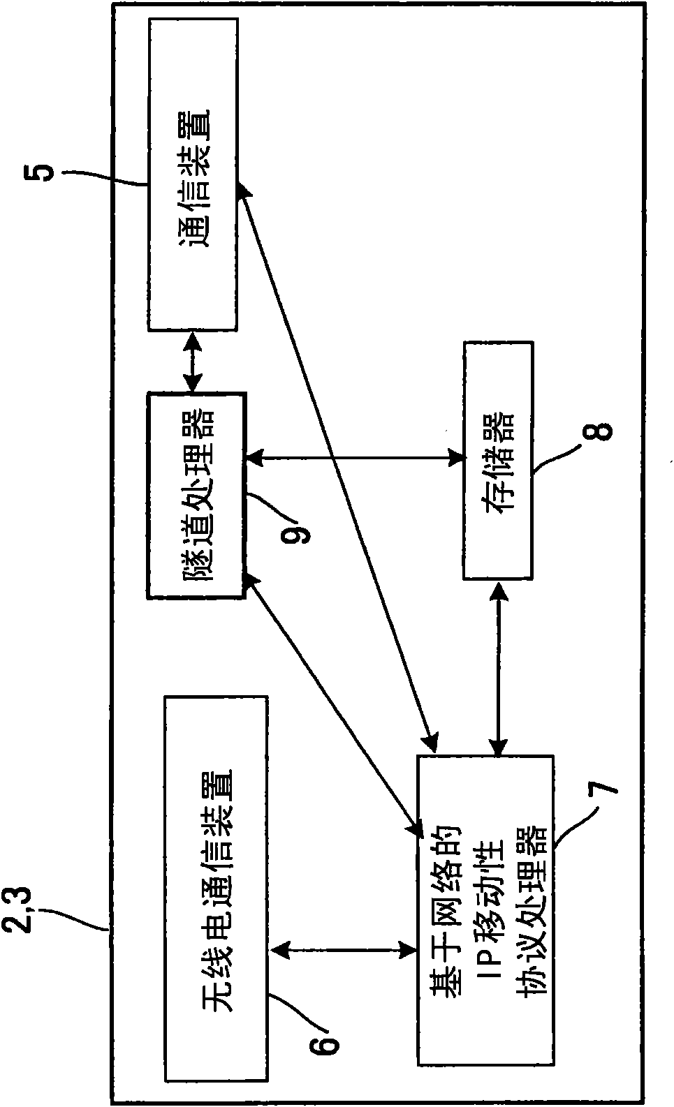
[0129] image 3 is a block diagram showing the configuration of the MAG in this embodiment.
[0130] Figure 4 is a block diagram showing the configuration of the LMA in this embodiment.
[0131] Such as figure 1 As shown, initially, MN 1 is under the control of MAGa 2 . Assume that MN 1 transfers from control of MAGa 2 to control of MAGb 3 while moving.
[0132] Below, will describe image 3 MAG in and Figure 4 LMA in.
[0133] Such as image 3 As shown, the MAGs 2 and 3 are configured to include: a communication device 5, which communicates with the LMA 4 through wired paths such as LAN (Local Area Network), the Internet, etc.; a radio communication device 6, which communicates wirelessly with the MN 1; a network-based IP A mobility protocol processor 7, which execu...
no. 2 example
[0170] Figure 8 is a diagram showing a schematic configuration of a network in this embodiment
[0171] Figure 9 is a sequence diagram showing procedural steps of processing in this embodiment.
[0172] Figure 10 is a block diagram showing the configuration of the MAG in this embodiment.
[0173] Figure 11 is a block diagram showing the configuration of the LMA in this embodiment.
[0174] Similar to the first embodiment, as Figure 8 As shown, it is assumed that MN 1 initially under the control of MAGa 2 transfers from the control of MAGa 2 to the control of MAGb 3 as it moves.
[0175] The present embodiment will be described assuming that handover based on the Proxy Mobile IP scheme is realized.
[0176] exist Figure 8 In , the AAA server 15 is connected to MAGa 2 and MAGa 3 via a network.
[0177] Such as Figure 10 As shown, similarly to the first embodiment, MAGb 2 and 3 are configured to include: communication means 5 for communicating with LMA 4 and AAA ...
no. 3 example
[0203] Figure 12 is a diagram showing a schematic configuration of a network in this embodiment.
[0204] Figure 13 is a sequence diagram showing procedural steps of processing in this embodiment.
[0205] In this embodiment, the MN has two addresses. Also, for each of these two addresses, a permanent ID and a temporary ID are provided as MN-ID. Furthermore, this embodiment can be implemented without giving any header compression information specifically to the MAG.
[0206] Such as Figure 12 As shown, initially, MN 1 is under the control of MAGa 2 . Assume that MN 1 transfers from control of MAGa 2 to control of MAGb 3 while moving.
[0207] First, if Figure 13 As shown, in S301, MN 1 sends address configuration information including at least MN-T-ID1 as a temporary identifier of MN 1 and LMAa-ID (ID of LMAa 18 managing MN-T-ID1). Similarly, MN 1 also transmits address configuration information including at least MN-T-ID2 as a temporary identifier of MN 1 and LMAb...
PUM
 Abstract
Description
Claims
Application Information
 - R&D
- Intellectual Property
- Life Sciences
- Materials
- Tech Scout
- Unparalleled Data Quality
- Higher Quality Content
- 60% Fewer Hallucinations
Browse by: Latest US Patents, China's latest patents, Technical Efficacy Thesaurus, Application Domain, Technology Topic, Popular Technical Reports.
© 2025 PatSnap. All rights reserved.Legal|Privacy policy|Modern Slavery Act Transparency Statement|Sitemap|About US| Contact US: help@patsnap.com


