Movable support frame

A support frame and support arm technology, applied in door/window accessories, wing leaf parts, buildings, etc., can solve the problem of no support, etc., to achieve the effect of ensuring normal rotation and convenient installation

Inactive Publication Date: 2010-03-31
JIANGSU YINHE ELECTRONICS
View PDF7 Cites 1 Cited by
  • Summary
  • Abstract
  • Description
  • Claims
  • Application Information

AI Technical Summary

Problems solved by technology

[0002] As we all know, the current rotating bodies (such as side doors) are usually movably connected to the supporting body through connecting parts such as rotating shafts or hinges arranged on one side, while there is no support on the opposite side.

Method used


Image

  • Movable support frame
  • Movable support frame

Examples


Embodiment Construction

[0010] Specific embodiments of the present invention will be described in detail below in conjunction with the accompanying drawings.

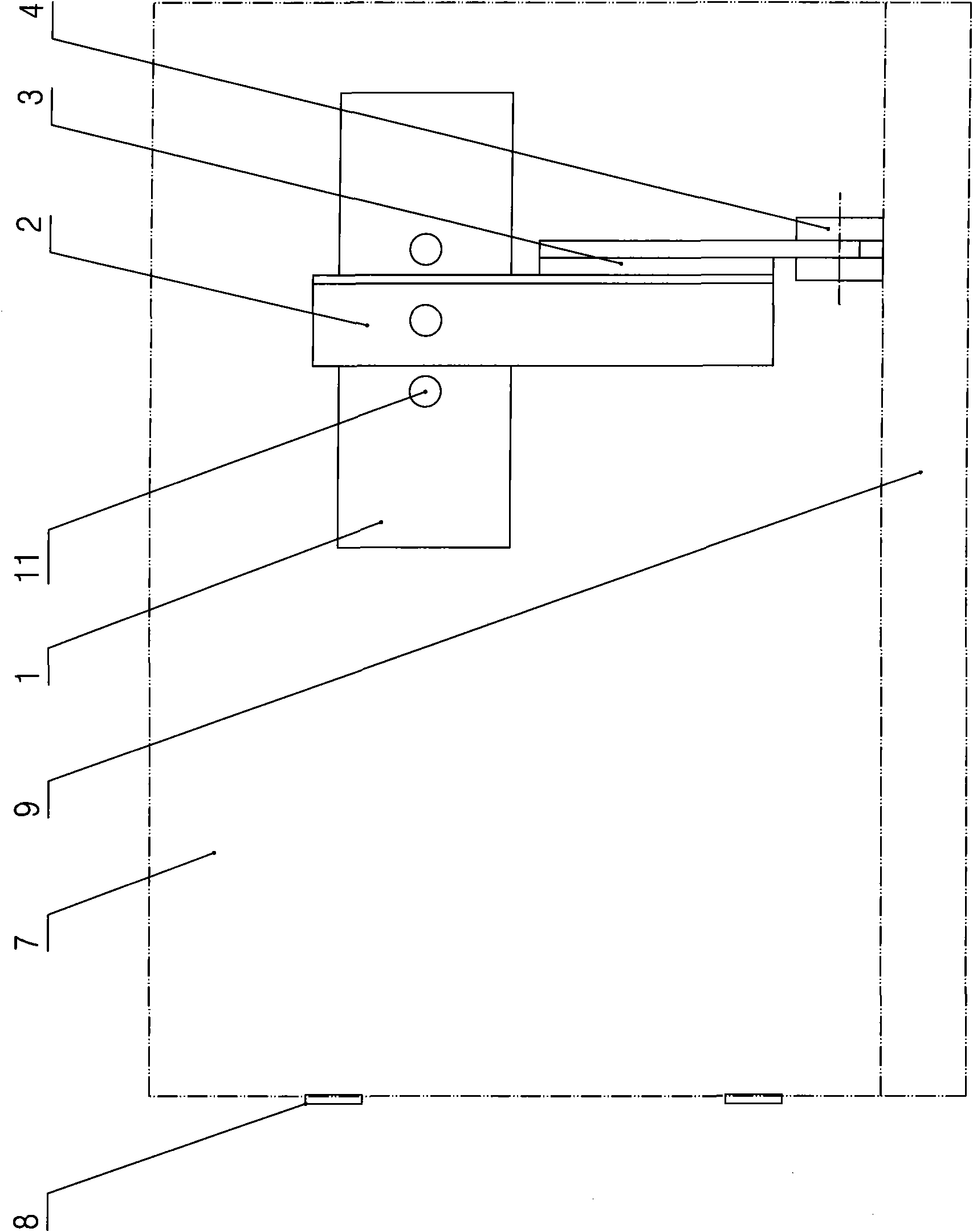
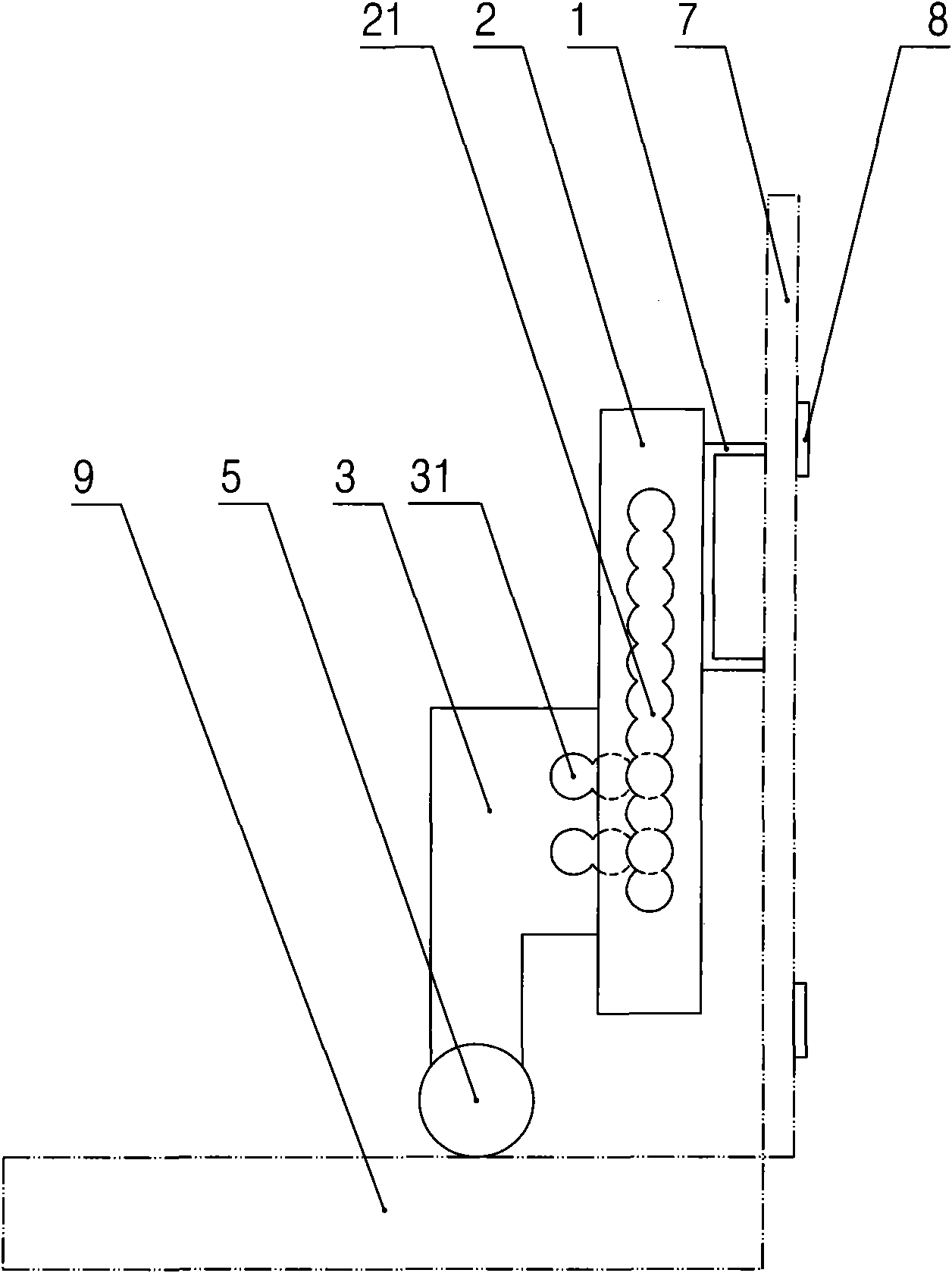
[0011] Such as figure 1 , figure 2 As shown, a movable support frame according to the present invention includes: a connecting plate 1 and a support arm, and the support arm includes a horizontal adjustment member 2, a vertical adjustment member 3 and positioning bolts, and a row of The upper and lower adjustment holes 21 in the vertical direction, the center distances between the adjacent upper and lower adjustment holes 21 are all equal, the vertical adjustment member 3 is provided with two rows of left and right adjustment screw holes 31 in the horizontal direction, and between the two rows of left and right adjustment screw holes 31 The center distance is twice the center distance between the adjacent upper and lower adjustment holes 21, and each positioning bolt is respectively arranged in an upper and lower adjustment hole and a left a...


PUM


Abstract

The invention discloses a movable support frame which can support a rotator so as to prevent the rotator from drooping. The movable support frame comprises a connection plate and a supporting arm, wherein the supporting arm comprises a horizontal adjusting part, a vertical adjusting part and a positioning bolt, a row of up and down adjusting holes in the vertical direction is arranged on the horizontal adjusting part, the distances between centers of every two adjacent up and down adjusting holes are equal, at least two rows of left and right adjusting screwed holes in the horizontal direction are arranged on the vertical adjusting part, the distance between centers of the two rows of left and right adjusting screwed holes is a multiple of the distance between centers of every two adjacent up and down adjusting holes, the positioning bolt is arranged in one up and down adjusting hole and one left and right adjusting screwed hole, and the bottom of the vertical adjusting part is provided with trolley wheels. The invention is mainly used to large-sized rotators.

Description

technical field [0001] The invention relates to a movable support frame. Background technique [0002] As we all know, the current rotating bodies (such as side doors) are usually movably connected to the supporting body through connecting parts such as rotating shafts or hinges arranged on one side, while there is no support on the opposite side. When the size or weight of the rotating body is large, the unsupported side of the rotating body will gradually sag due to the action of gravity during the rotating process. When the sag accumulates to a certain extent, the rotation will be difficult. Contents of the invention [0003] A technical problem to be solved by the present invention is to provide a movable support frame capable of supporting the rotating body so as to prevent the rotating body from sagging. [0004] In order to solve the above technical problems, the technical solution adopted by the present invention is: a movable support frame, including: a connectin...

Claims


Application Information

Patent Timeline
Patent Type & Authority Applications(China)
IPC IPC(8): E05F7/06
Inventor 李守全
Owner JIANGSU YINHE ELECTRONICS
Why Eureka
Try Eureka