Blanking floating cutter structure and blanking die with same

A floating knife and blanking die technology, applied in the field of blanking dies, can solve problems such as burrs and waste, scrapped blanking parts, and coil deformation

Inactive Publication Date: 2021-06-01
DONGFENG MOTOR CORP HUBEI
View PDF5 Cites 0 Cited by
  • Summary
  • Abstract
  • Description
  • Claims
  • Application Information

AI Technical Summary

Problems solved by technology

Although this solution can avoid the problem of mold interference at the intersection of the sides of the trimming plate, there will also be a difference in height between the corner cutting edge of the punch and the corner cutting edge, resulting in no support for the coil material in the avoidance area. When the edge trimming knife corresponding to the edge cutting edge goes down When , the coil material in the avoidance area lacking support will be deformed
When the coiled material advances through the avoidance area, it will be scratched by the avoiding edge, resulting in scratches. At the same time, because the coiled material is deformed during the trimming process, the trimming surface will scratch the trimming knife during the deformation process, resulting in burrs and waste. Chips adsorbed on the trimming knife and the punch will further scratch the sheet, resulting in more scratches, resulting in the scrapping of blanked parts

Method used


Image

  • Blanking floating cutter structure and blanking die with same
  • Blanking floating cutter structure and blanking die with same
  • Blanking floating cutter structure and blanking die with same

Examples


Embodiment Construction

[0024] The present invention will be further described in detail below in conjunction with the accompanying drawings and specific embodiments.

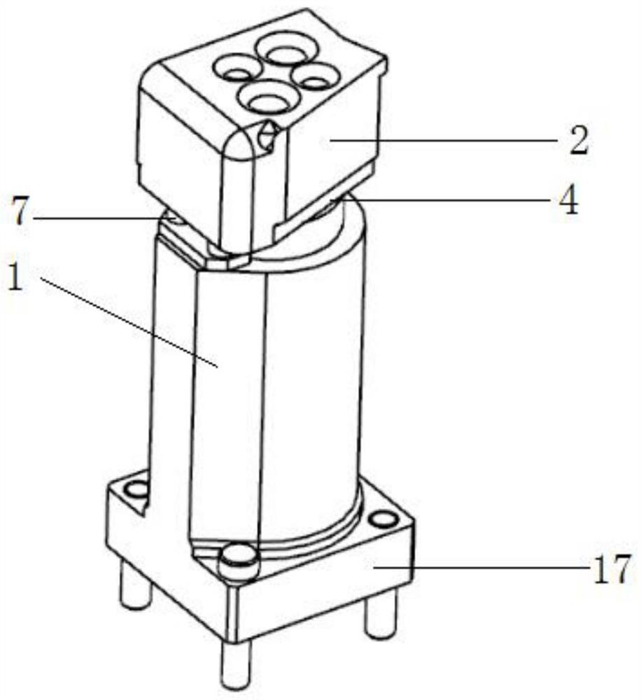
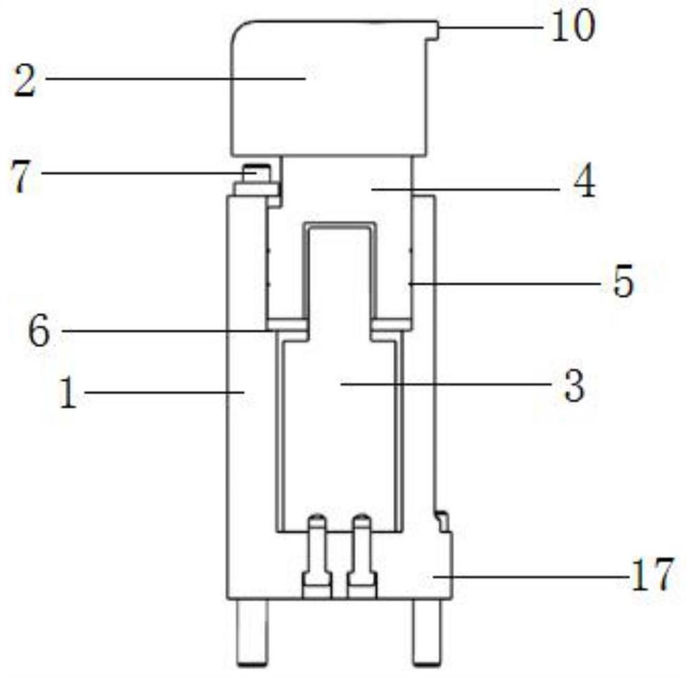
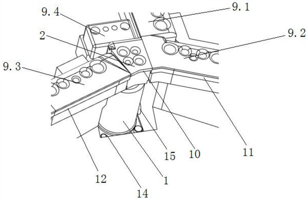
[0025] Such as figure 1 - The blanking floating knife structure shown in 2 includes a sleeve 1, a spring 3 and a drive block 4 coaxially fixed on the top of the spring 3 are coaxially arranged in the sleeve 1, and the bottom of the spring 3 is fixed to the sleeve 1 by screws Inside, the floating punch 2 is fixed on the top of the driving block 4, and one side surface of the floating punch 2 is provided with a floating chamfering surface 10 that can cooperate with the edge of the trimming knife, and the driving block 4 is coaxially fixed on the spring 3 The cylindrical driving block on the top, the upper annular inner surface of the sleeve 1 and the circumferential surface of the driving block 4 are clearance fit to avoid the radial shaking of the driving block 4. Lubricating oil is injected inside to ensure the stability of the axia...


PUM


Abstract

The invention discloses a blanking floating cutter structure and a blanking die with the same. The blanking floating cutter structure comprises a sleeve; an elastic driving structure which can stretch out and draw back in the axial direction and reset automatically is coaxially arranged in the sleeve; the top of the elastic driving structure penetrates through the sleeve to be fixedly provided with a floating male die; the bottom of the elastic driving structure is fixed in the sleeve; a floating corner trimming face capable of being matched with a knife edge of a trimming knife is arranged on the surface of one side of the floating male die; and a radial limiting structure for limiting shaking of the elastic driving structure is arranged in the sleeve. By arranging the floating cutter structure, the problem that the trimming knife and the male die interfere with each other is solved, and meanwhile the problem of high cost of multi-step production and the quality problem caused by the height difference of the male die are solved. The floating cutter structure is small in size and is only located in the interference area of the trimming knife and the male die, so that the floating cutter structure is suitable for machining workpieces with different included angles, the distance between material brackets cannot be too large, and it is guaranteed that a plate does not droop.

Description

technical field [0001] The invention relates to the technical field of stamping parts forming equipment, in particular to a blanking floating knife structure and a blanking die with a blanking floating knife structure. Background technique [0002] Stamping parts are obtained from sheet metal through stamping process. Simple stampings generally use trapezoidal sheets, which are obtained by pendulum shearing. For stamping parts with complex shapes, the trapezoidal sheet material has a large gap with the part contour, and the flow is uneven during the forming process, which cannot meet the production requirements. The blanking die must be used to process the coil material to obtain blanking parts whose shape matches the part contour Used for stamping production, its shape is generally polygonal and may have process holes. Blanking die is a mold used to process coil materials. Generally, it has multiple steps similar to progressive die. It is composed of upper die and lower d...

Claims


Application Information

Patent Timeline
Patent Type & Authority Applications(China)
IPC IPC(8): B21D28/14
CPCB21D28/14
Inventor 曹琰朱念徐宏文韦衍杰王景瑞
Owner DONGFENG MOTOR CORP HUBEI
Why Eureka
Try Eureka