Rotary compressor and freezing cycle device using the same

A technology of rotary compressors and compression mechanisms, applied in the direction of rotary piston machines, compressors, rotary piston pumps, etc., can solve problems such as compression performance degradation, achieve the effects of suppressing sliding loss and eliminating insufficient rigidity

Active Publication Date: 2010-03-31
TOSHIBA CARRIER CORP
View PDF1 Cites 15 Cited by
  • Summary
  • Abstract
  • Description
  • Claims
  • Application Information

AI Technical Summary

Problems solved by technology

[0006] Therefore, when designing the outer and inner diameters and axial length of the eccentric roller, the shaft diameter and axial length of the eccentric part of the rotating shaft, consideration should be given to suppressing the sliding loss between the eccentric part of the rotatin

Method used


Image

  • Rotary compressor and freezing cycle device using the same
  • Rotary compressor and freezing cycle device using the same
  • Rotary compressor and freezing cycle device using the same

Examples


Embodiment Construction

[0025] Embodiments of the present invention will be described below with reference to the drawings.

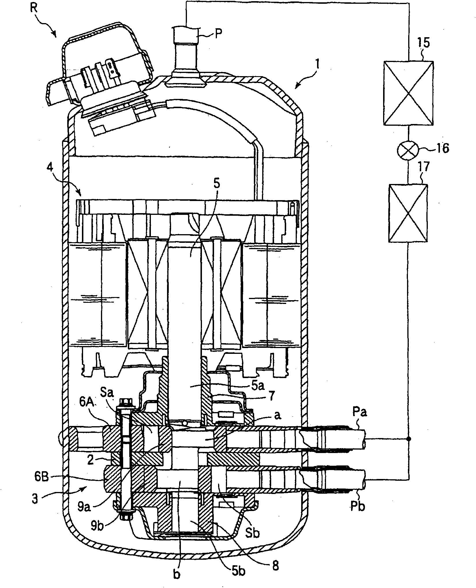
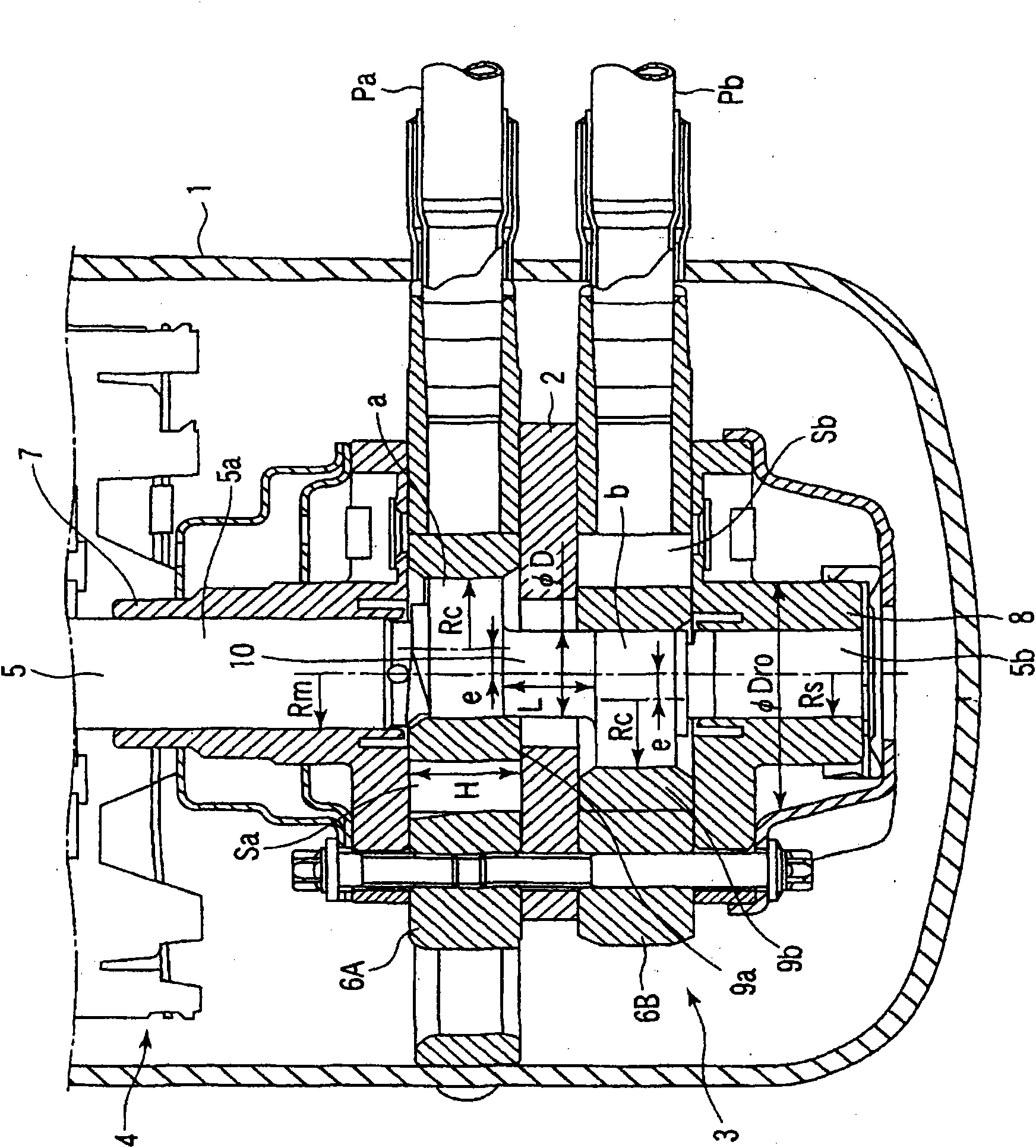
[0026] figure 1 It is a vertical cross-sectional view and a refrigeration cycle configuration diagram of the refrigeration cycle apparatus with a part of the rotary compressor R omitted. figure 2 It is an enlarged longitudinal sectional view of the main part of the rotary compressor (In order to avoid complicating the drawings, there are parts that are described but not marked, and there are also parts that are shown but not described. The same applies to the following) .

[0027] First, the rotary compressor R will be described, and reference numeral 1 is an airtight container, and the compression mechanism part 3 is provided in the lower part of the airtight container 1, and the motor part 4 is provided in the upper part. The compression mechanism unit 3 and the motor unit 4 are connected by a shaft 5 .

[0028] The compression mechanism unit 3 has a first cylinder 6A on...


PUM


Abstract

The invention provides a rotary compressor and a freezing cycle device which can inhibit slippage loss of an eccentric part of a rotating shaft and an eccentric roller, prevent flexible deformation and improve compression performance. The structure of the rotary compressor comprises that: the radius of the eccentric part of the rotating shaft is set to be Rc, the radius of a main shaft part is Rm,the radius of an auxiliary shaft part is Rs, the eccentricity of the eccentric part is e, a formula 1 which is Rc<Rm+e is satisfied, and a formula 2 which is Rc>=Rs+e is satisfied; the shaft length of a connecting part is L, the diameter of a shaft of the connecting part is phiD, and the shaft length (thickness) of the eccentric roller is H, a formula 3 which is (2L-H)/(D+2e)>=0.5 is satisfied; the differential pressure of a discharge pressure and a suction pressure is deltaP, the outer diameter of the eccentric roller is phiDro, the Young modulus of the rotating shaft is E, section moment ofinertia of the connecting part is M, the cylinder inner diameter of the connecting part is Di, and a formula 4 which is (deltaP*Dro*H*L<3>)/(E*M)<=0.02mm, wherein M=pi*(D<4>-Di<4>)/64.

Description

technical field [0001] The present invention relates to a rotary compressor having a plurality of cylinder chambers and a refrigerating cycle device having such a rotary compressor constituting a refrigerating cycle. Background technique [0002] As a rotary compressor used in air conditioners and refrigerators, the rotary compressor disclosed in Patent Document 1 is a single-cylinder type rotary compressor having one compression mechanism, where the inner diameter of the cylinder chamber is Dcy , the height (axial length) of the cylinder is H, the shaft diameter of the eccentric portion of the rotating shaft is Dcr, and the axial sliding length (contact length) between the eccentric portion of the rotating shaft and the eccentric roller is L, H / Dcy≤0.4 and The structure of L / Dcr≥0.6, so as to realize the improvement of efficiency. [0003] Patent Document 1: Japanese Patent Laid-Open No. 2008-14150 [0004] In the single-cylinder rotary compressor described in this patent...

Claims


Application Information

Patent Timeline
IPC IPC(8): F04C18/00F25B1/04
Inventor 平山卓也北市昌一郎池田亘富永健池田明贵范
Owner TOSHIBA CARRIER CORP
Why Eureka
Try Eureka