Transmission mechanism

a transmission mechanism and transmission shaft technology, applied in the direction of friction gearings, belts/chains/gearings, friction gearings, etc., can solve the problems of slippage (slip loss) between the drive roller, the mechanism is prone to become large, and the weight and noise increase, so as to achieve high speed-varying ratio, low cost, and small size

Inactive Publication Date: 2010-04-22
SHONAN INSTITUTE OF TECHNOLOGY +1
View PDF2 Cites 0 Cited by
  • Summary
  • Abstract
  • Description
  • Claims
  • Application Information

AI Technical Summary

Benefits of technology

[0031]According to the present invention, by using a small diameter rolling element and a large diameter rolling element, it is possible to realize a high speed-varying ratio, and it becomes possible to achieve small size, low cost and low noise. Also, by using a supplementary rolling element and a pressure adjustment ring, it is possible to suppress slip loss between the small diameter rolling element and the large diameter rolling element.

Problems solved by technology

in order to obtain a high reduction ratio, it is necessary to combine a lot of gears, which means there is a tendency for the mechanism to become large in size
if a lot of gears are used, the weight and noise are increased.
Also, in transmission mechanisms using rollers there are drawbacks such as:
in the case of high load, it is easy for slippage (slip loss) to arise between a drive roller and a driven roller
if a biasing mechanism for limiting slippage is provided, the mechanism becomes complicated

Method used


Image

  • Transmission mechanism
  • Transmission mechanism
  • Transmission mechanism

Examples


first embodiment

Structure of First Embodiment

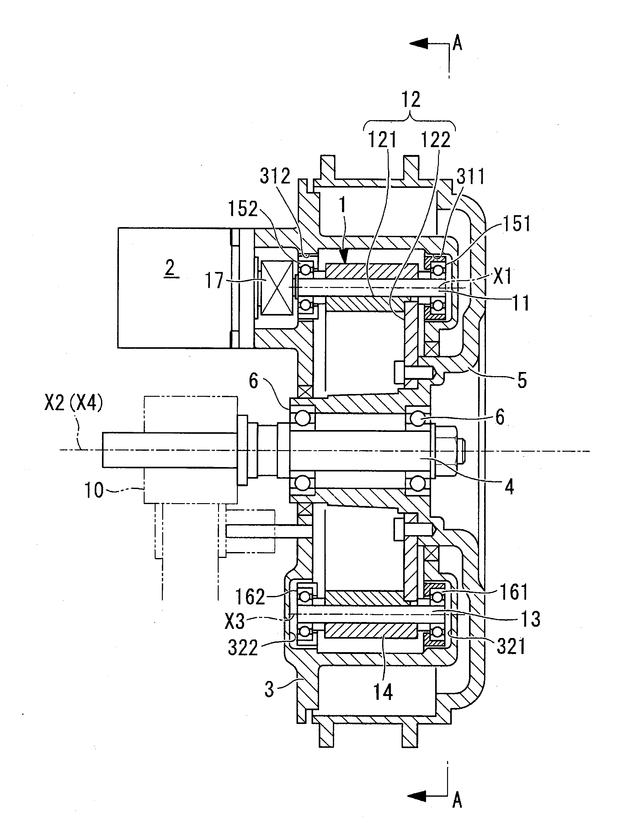
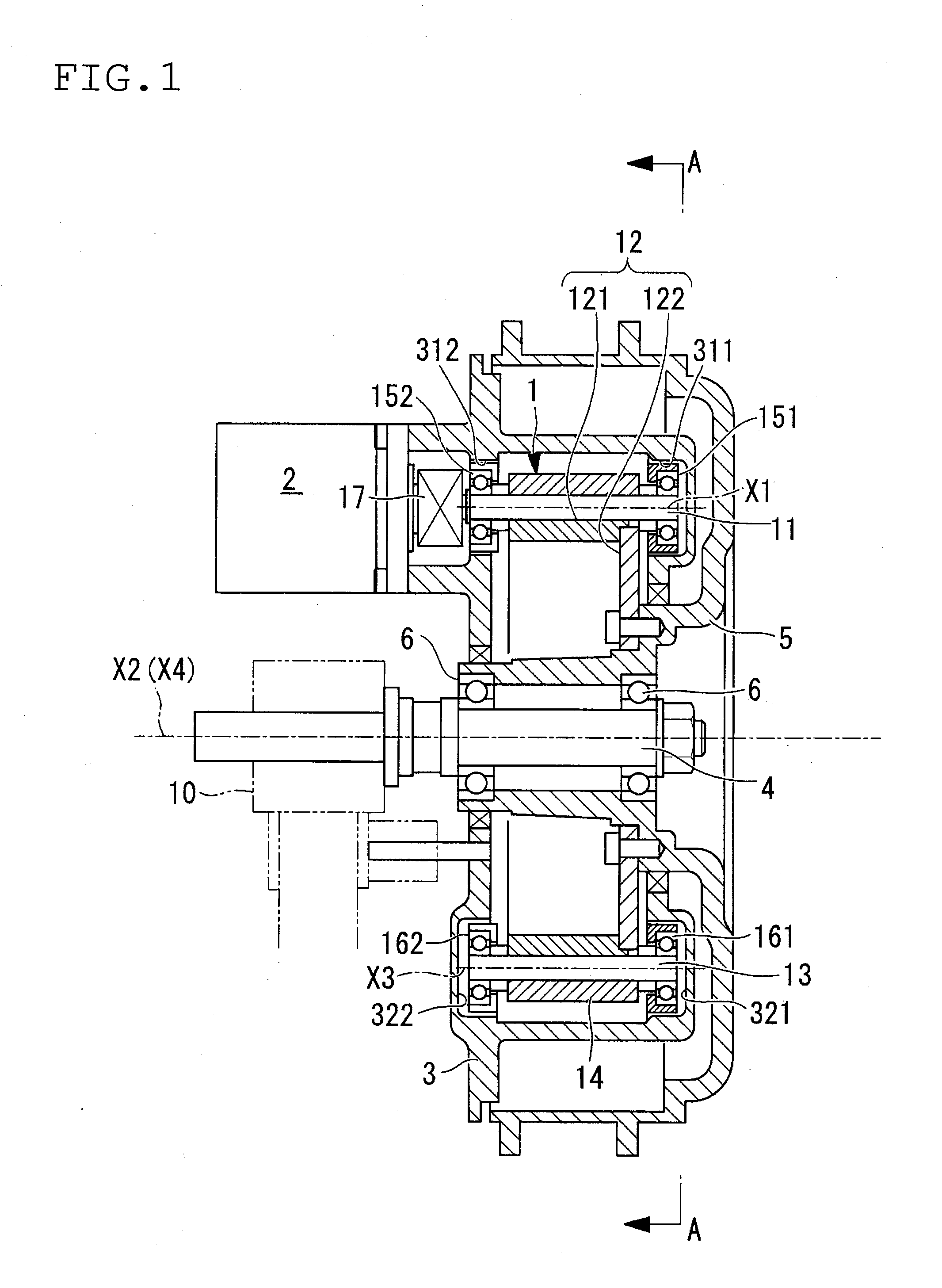
[0041]The wheel drive unit of this embodiment comprises a transmission unit 1, drive source 2, support body 3, axle 4, hub (axle support section) 5 and bearing 6 as main components.

Structure of Transmission Unit of this Embodiment

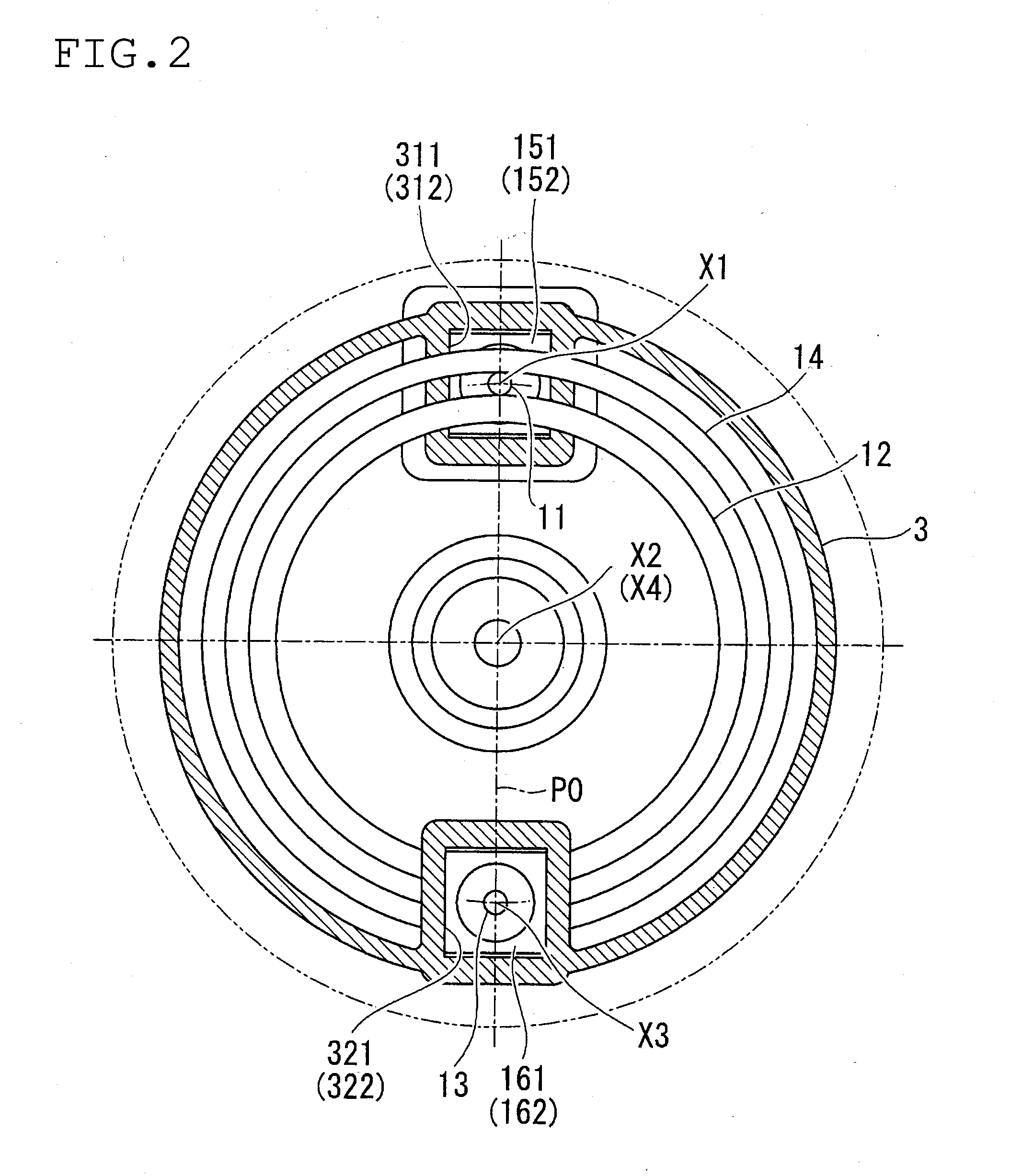
[0042]A transmission unit 1 is provided with a small diameter rolling element 11, a large diameter rolling element 12, a supplementary rolling element 13, and a pressure adjustment ring 14, as main components.

[0043]The small diameter rolling element 11 is capable of rotation with a first virtual axis of rotation X1 as a center. In more detail, both end sections of the small diameter rolling element 11 are supported by bearings 151 and 152 (refer to FIG. 1), and the small diameter rolling element 11 is thus rotatable about the axis.

[0044]Also, one end of the small diameter rolling element 11 is connected by means of a universal joint 17 to the drive source 2. In this way the small diameter rolling element 11 is connected to the d...

second embodiment

[0093]Next, a wheel drive unit using a transmission unit of a second embodiment of the present invention will be described based on FIG. 4. In the description of this embodiment, structural elements that are basically common to the first embodiment described above have the same reference numerals attached, and description will be simplified.

[0094]With the transmission unit 1 of the second embodiment, the first and second virtual axes of rotation X1 and X2 are arranged on a first virtual plane P1. On the other hand, the second and third virtual axes of rotation X2 and X3 are arranged on a second virtual plane P2.

[0095]Here, an external angle θ formed by the first plane P1 and the second plane P2 is set to 0<θ≦20 (refer to FIG. 4). Here, if internal angle is made α, then it is possible to represent the external angle θ as follows:

θ=180°−α

(refer to FIG. 4).

[0096]Specifically, with the second embodiment the position of the supplementary rolling element 13 has been moved compared to the ...

third embodiment

[0103]Next, a power transmission unit using a transmission unit of a third embodiment of the present invention will be described based on FIG. 5 and FIG. 6. In the description of this embodiment, structural elements that are basically common to the first embodiment described above have the same reference numerals attached, and description will be omitted.

[0104]The power transmission unit of the third invention comprises a transmission unit 1, a casing 30, an output shaft 40, and two bearings 60.

[0105]A transmission section 122 of the transmission unit 1 of the third embodiment is fixed to the output shaft 40. The output shaft 40 is rotatably attached to the casing 30 by means of the bearings 60.

[0106]Also, the casing 30, similarly to the first embodiment, is provided with slits 3011 and 3012 for attachment of the bearings 151 and 152 for the small diameter rolling element 11, and slits 3021 and 3022 for attachment of the bearings 161 and 162 for the supplementary rolling element 13....


PUM


Abstract

The present invention provides a transmission unit that can realize a high speed-shifting ratio, can realize reduced size, low cost and low noise, and is also capable of limiting slip loss. Outer peripheral surfaces of a small diameter rolling element and a supplementary rolling element are brought into contact with an outer peripheral surface of a large diameter rolling element. The supplementary rolling element is arranged at an almost opposite side to the small diameter rolling element, thus enclosing the large diameter rolling element between the small diameter rolling element and the supplementary rolling element. An inner peripheral surface of the pressure adjustment ring is brought into contact with the outer peripheral surface of the small diameter rolling element and the outer peripheral surface of the supplementary rolling element, and is supported by them. If the small diameter rolling element rotates, the pressure adjustment ring rotates by means of the large diameter rolling element and the supplementary rolling element. If load is applied to rotation of the large diameter rolling element, the pressure adjustment ring is made eccentric. In this way, the small diameter rolling element receives pressing force toward an inner side in the radial direction of the large diameter rolling element, from the pressure adjustment ring.

Description

TECHNICAL FIELD[0001]The present invention relates to a transmission mechanism used mainly in transmission of power.BACKGROUND ART[0002]Examples of transmission mechanisms are disclosed in the following publications, patent publications 1 to 6, for example. Transmission in the context of this specification collectively means both gearing up and gearing down.[0003]The technology disclosed in these publications can be those using toothed gears (patent publication 3, for example) and those using rollers (for example, patent publication 4).[0004]In a transmission mechanism using toothed gears, there are the drawbacks such as:[0005]in order to obtain a high reduction ratio, it is necessary to combine a lot of gears, which means there is a tendency for the mechanism to become large in size[0006]if a lot of gears are used, the weight and noise are increased.[0007]Also, in transmission mechanisms using rollers there are drawbacks such as:[0008]in the case of high load, it is easy for slippa...

Claims


Application Information

Patent Timeline
Patent Type & Authority Applications(United States)
IPC IPC(8): F16H15/50
CPCF16H13/06F16H13/02
Inventor MURAKI, MASAYOSHIOKAMURA, KIKUO
Owner SHONAN INSTITUTE OF TECHNOLOGY
Why Eureka
Try Eureka