Fuel pump

A fuel pump and fuel technology, which is applied to fuel injection pumps, pumps, fuel injection devices, etc., can solve problems such as fuel pressure imbalance and adverse effects on pump efficiency.

Active Publication Date: 2017-09-26
DENSO CORP
View PDF7 Cites 0 Cited by
  • Summary
  • Abstract
  • Description
  • Claims
  • Application Information

AI Technical Summary

Problems solved by technology

However, when this structure is applied to a fuel pump, the fuel pressure in the fuel chamber between the recesses is unbalanced due to the difference in the amount of fuel leakage on both sides in the axial direction. Friction, which adversely affects pump efficiency

Method used


Image

  • Fuel pump
  • Fuel pump
  • Fuel pump

Examples


Embodiment Construction

[0023] Hereinafter, one embodiment will be described based on the drawings.

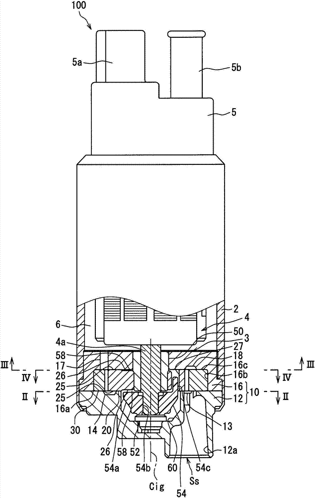
[0024] Such as figure 1 As shown, the fuel pump 100 according to one embodiment is a positive displacement trochoidal pump mounted on a vehicle. The fuel pump 100 includes a pump main body 3 and an electric motor 4 housed in a cylindrical pump body 2 . At the same time, the fuel pump 100 includes a side cover 5 protruding to the outside from the end opposite to the pump main body 3 , sandwiching the electric motor 4 in the pump body 2 in the axial direction. Here, the side cover 5 includes an electrical connector 5a for supplying electricity to the electric motor, and a discharge port 5b for discharging fuel. In such a fuel pump 100 , the electric motor 4 is rotationally driven by energization from an external circuit via the electrical connector 5 a. As a result, the fuel sucked and pressurized by the pump main body 3 by the rotational force of the rotary shaft 4 a of the electric motor 4 is dis...


PUM


Abstract

An inner gear (20) has: sliding surface sections (25) provided on both axial sides of the inner gear (20), the sliding surface sections (25) sliding on a pump housing (10) and being provided in an annular manner in an outer peripheral section (24) that includes outer teeth (24a); recess sections (26) provided more peripherally inward than the sliding surface sections (25), the recess sections (26) forming a fuel-inflow fuel chamber (58) with the pump housing (10); communication holes (27) for allowing communication between the recess sections (26); and inclined surface sections (29) in which the portions of the inclined surface sections (29) located more toward the center section of the communication holes (27) are inclined progressively more inward, the communication holes (27) being provided to the edge sections of the inner gear (20) on the side to which the inner gear (20) advances when rotating, the inclined surface sections (29) being provided to communication edge sections (28) that are edge sections of openings in communication with the recess sections (26) in the communication holes (27), the inclined surface sections (29) being provided in areas that do not include the adjacent locations (28a, 28b, 28c) adjacent to the inner peripheral edge section (25a) of the sliding surface sections (25).

Description

[0001] This application is based on Japanese Patent Application No. 2015-6177 filed on January 15, 2015, the entire content of which is incorporated herein. technical field [0002] The present invention relates to a fuel pump that sequentially sucks fuel into each pump chamber and then discharges it. Background technique [0003] Conventionally, Patent Document 1 discloses a pump that can be applied to a fuel pump that sequentially sucks and discharges fuel into a pump chamber. This pump includes: an external gear having a plurality of internal teeth; an internal gear having a plurality of external teeth meshing with the external gear eccentrically in an eccentric direction; and a pump case rotatably accommodating the external gear and the internal gear. The external gear and the internal gear rotate while expanding and contracting the volume of a plurality of pump chambers formed between the two gears, and sequentially suck oil into each pump chamber and then discharge it....

Claims


Application Information

Patent Timeline
Patent Type & Authority Applications(China)
IPC IPC(8): F04C2/10F02M37/10F04C15/00
CPCF02M37/10F04C2/102F04C11/008F04C15/008F04C15/06F04C2210/203F02M59/12F04C2/10F04C15/00F04C2/084F04C2/086F04C15/0065F04C15/0088F04C2240/30F04C2240/40F04C2240/60
Inventor 酒井博美古桥代司
Owner DENSO CORP
Why Eureka
Try Eureka