Sealed compressor

A compressor, airtight technology, applied in the direction of mechanical equipment, machine/engine, liquid variable capacity machinery, etc., can solve the problem of severe sliding state

Inactive Publication Date: 2011-02-09
PANASONIC APPLIANCES REFRIGERATION DEVICES SINGAPORE
View PDF5 Cites 0 Cited by
  • Summary
  • Abstract
  • Description
  • Claims
  • Application Information

AI Technical Summary

Problems solved by technology

As a result, the outer peripheral surface of the piston 23 on the side that has not slipped on the tapered portion 17 before turning over contacts the tapered portion 17, and the sliding state becomes severe, and there is a possibility that contact noise may be generated when the contact during turning is severe.

Method used


Image

  • Sealed compressor
  • Sealed compressor
  • Sealed compressor

Examples


Embodiment approach 1

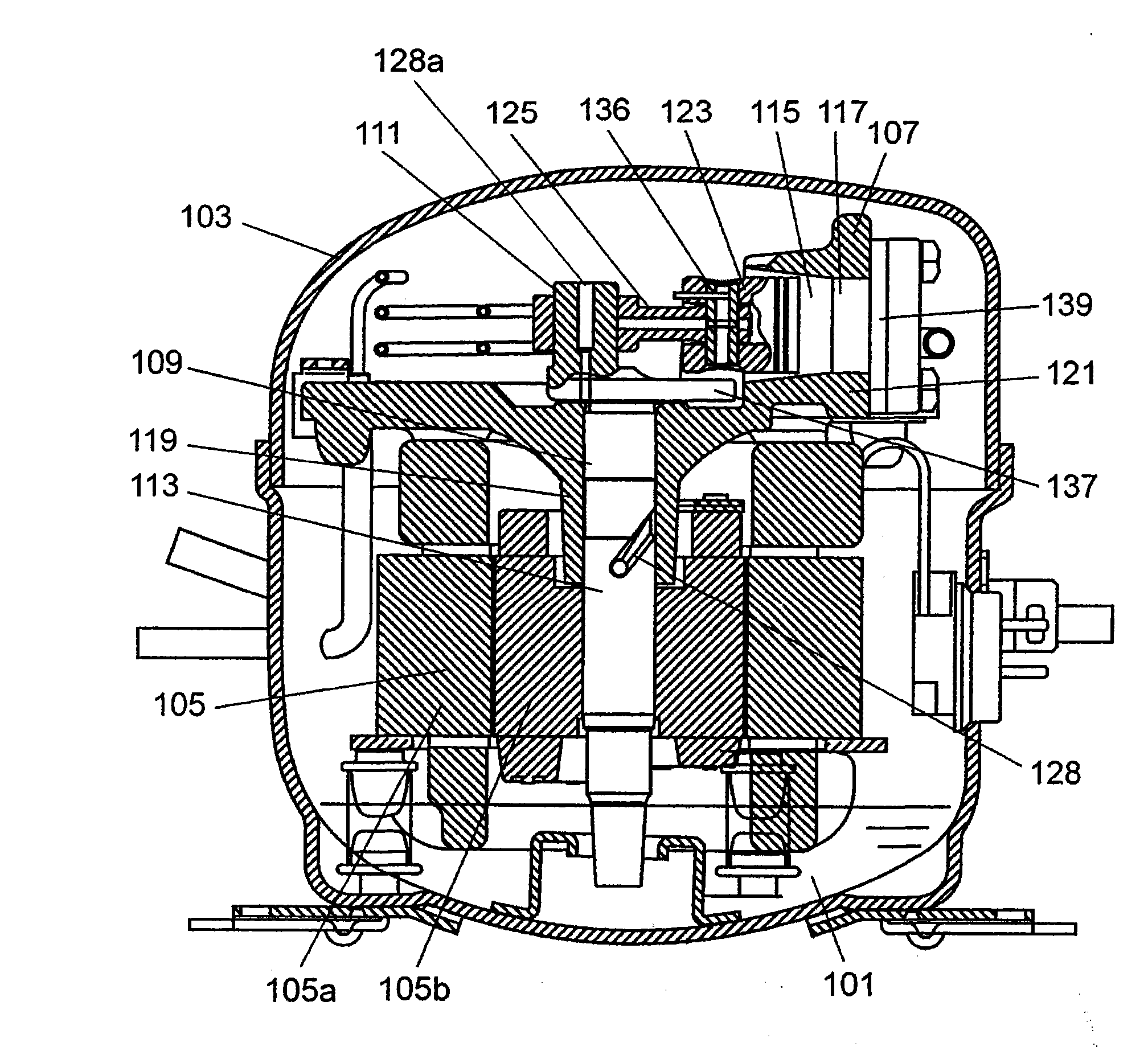
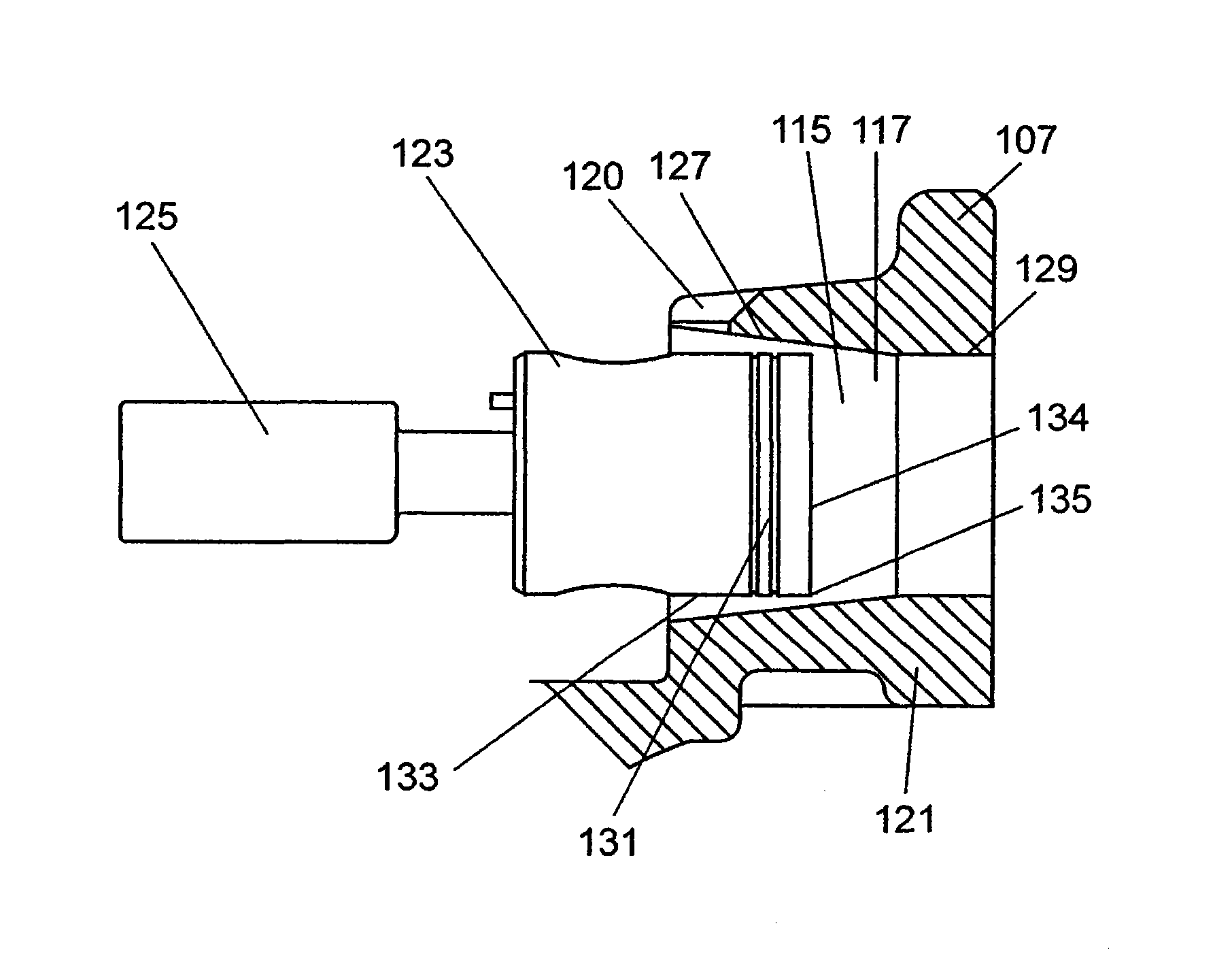
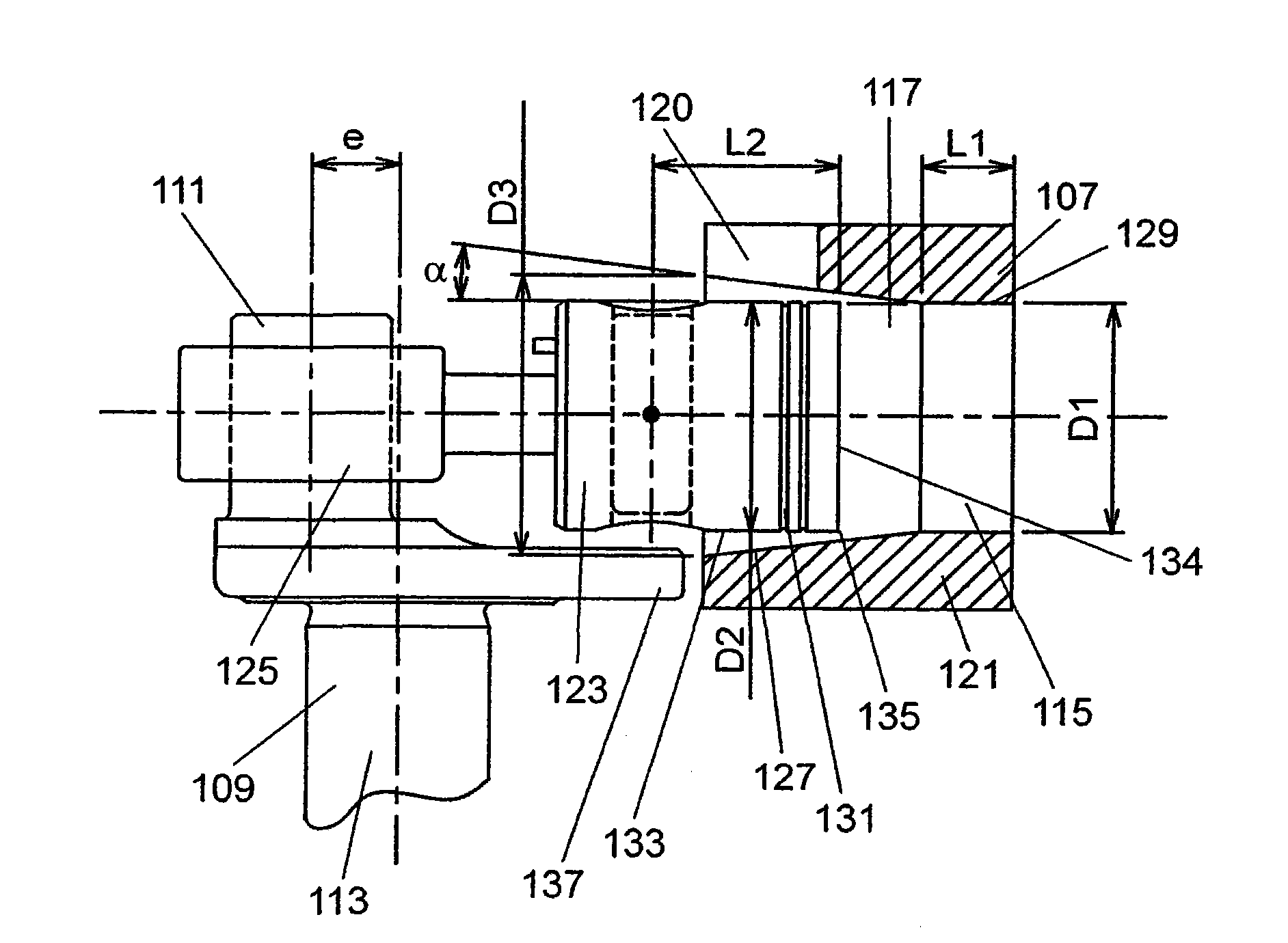
[0067] figure 1 It is a longitudinal sectional view of the hermetic compressor in Embodiment 1 of this invention. figure 2 It is a longitudinal sectional view of main parts of the compression part in this embodiment. image 3 It is a longitudinal sectional view of main parts showing various design elements of the compression part in this embodiment. Figure 4 It is a main part cross-sectional view showing various design elements of the compression part in this embodiment.

[0068] refer to Figure 1 to Figure 4 An electric component 105 including a stator 105 a and a rotor 105 b and a compression element 107 driven by the electric component 105 are housed in the airtight container 103 . Furthermore, lubricating oil 101 is also stored in the bottom of airtight container 103 . The shaft 113 has a main shaft part 109 and an eccentric shaft part 111 formed eccentrically at one end of the main shaft part 109 to move integrally with the main shaft part 109 . The main shaft po...

Embodiment approach 2

[0131] This embodiment differs from Embodiment 1 in the arrangement of the bearing portion 119 and the compression chamber 115 . Other configurations are the same as those in Embodiment 1. Therefore, in this embodiment, configurations different from those in Embodiment 1 will be mainly described.

[0132] Figure 10 It is a longitudinal sectional view of main parts showing various design elements of the compression part in this embodiment. Figure 11 It is a main part cross-sectional view showing various design elements of the compression part in this embodiment.

[0133] Such as Figure 10 , Figure 11 As shown, in this embodiment, the third centerline 142 parallel to the first centerline 141 representing the axis of the bearing portion 119 and the second centerline 143 representing the axis of the compression chamber 115 are arranged so that they intersect each other. A bearing portion 119 and a compression chamber 115 are provided. also, Figure 11 in, due to Figur...


PUM


Abstract

In a sealed compressor, a circular tube-shaped hole section (117) which forms a compression chamber (115) has a tapered section (127) formed in such a manner that the inner diameter of the tapered section (127) increases from the side on which a piston (123) is positioned at the upper dead center toward the side on which the piston (123) is positioned at the bottom dead center. The piston (123) is configured so that the direction of tilt thereof changes relative to the axis of the hole section (117) in the initial period of a compression stroke. As a result, the strength of contact between the piston (123) and the hole section (117) when the piston (123) changes the direction of tilt thereof is lower than the strength of the contact when the piston (123) changes the direction of tilt thereof in and after the middle period of the compression stroke. This makes the sealed compressor highly reliable and allows the sealed compressor to achieve reduced noise levels.

Description

technical field [0001] The present invention relates to a hermetic compressor used in refrigerating cycles of refrigerating cabinets and the like. Background technique [0002] For example, Patent Document 1 discloses a conventional hermetic compressor using a reciprocating type for a compression mechanism. The hermetic compressor disclosed in Patent Document 1 includes a cylinder body forming a compression chamber having a cylindrical inner diameter; a piston reciprocating in the cylinder body and having a cylindrical outer diameter; and a connecting rod having a cylindrical outer diameter. The eccentric shaft portion of the shaft is connected to the piston via a piston pin. Furthermore, the shaft is fixed to the shaft center of the rotor of the motor unit, and the compression mechanism is operated by the rotation of the rotor. [0003] Generally, in such a hermetic compressor, a clearance for sliding is required between the inner diameter of the cylinder and the outer di...

Claims


Application Information

Patent Timeline
Patent Type & Authority Applications(China)
IPC IPC(8): F04B39/00F04B39/12
CPCF04B39/125F04B39/126F04B39/023
Inventor 八木章夫森田一郎
Owner PANASONIC APPLIANCES REFRIGERATION DEVICES SINGAPORE
Why Eureka
Try Eureka