
Gas combustion type knock tool

A technology for driving tools and gas, applied in the direction of nailing tools, manufacturing tools, etc., can solve problems such as feed failure, hammering piston can not return, deformation of connecting materials, etc., to prevent return failure, eliminate friction, and simple structure Effect

Inactive Publication Date: 2010-03-31
MAX CO LTD
View PDF1 Cites 7 Cited by
  • Summary
  • Abstract
  • Description
  • Claims
  • Application Information

AI Technical Summary

Problems solved by technology

Therefore, there may be a problem that the hammering piston cannot return due to the contact resistance generated
Also, there is the possibility that the joining material joining the fasteners could deform causing feed failures

Method used


Image

  • Gas combustion type knock tool
  • Gas combustion type knock tool

Examples


Embodiment Construction

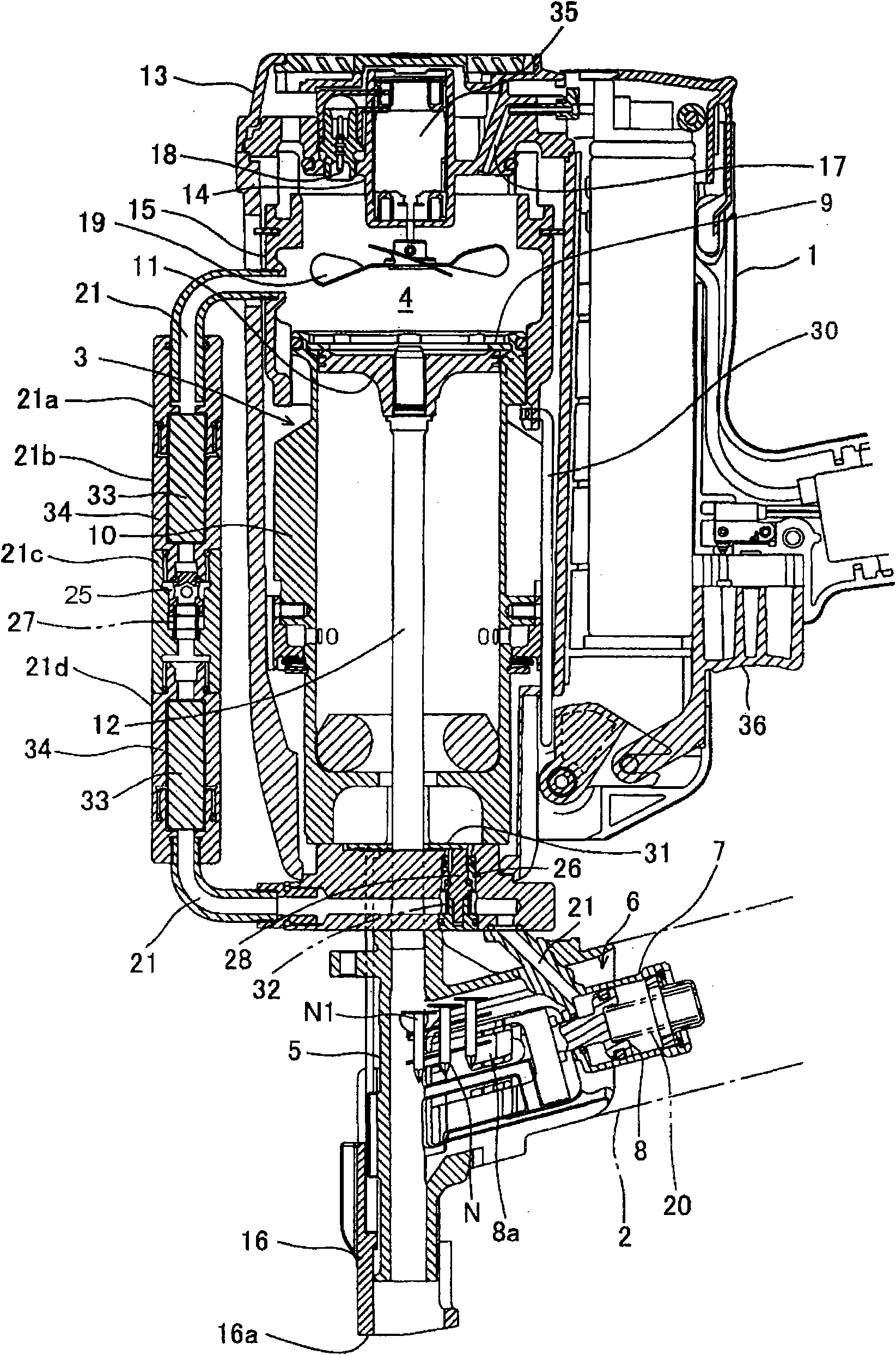
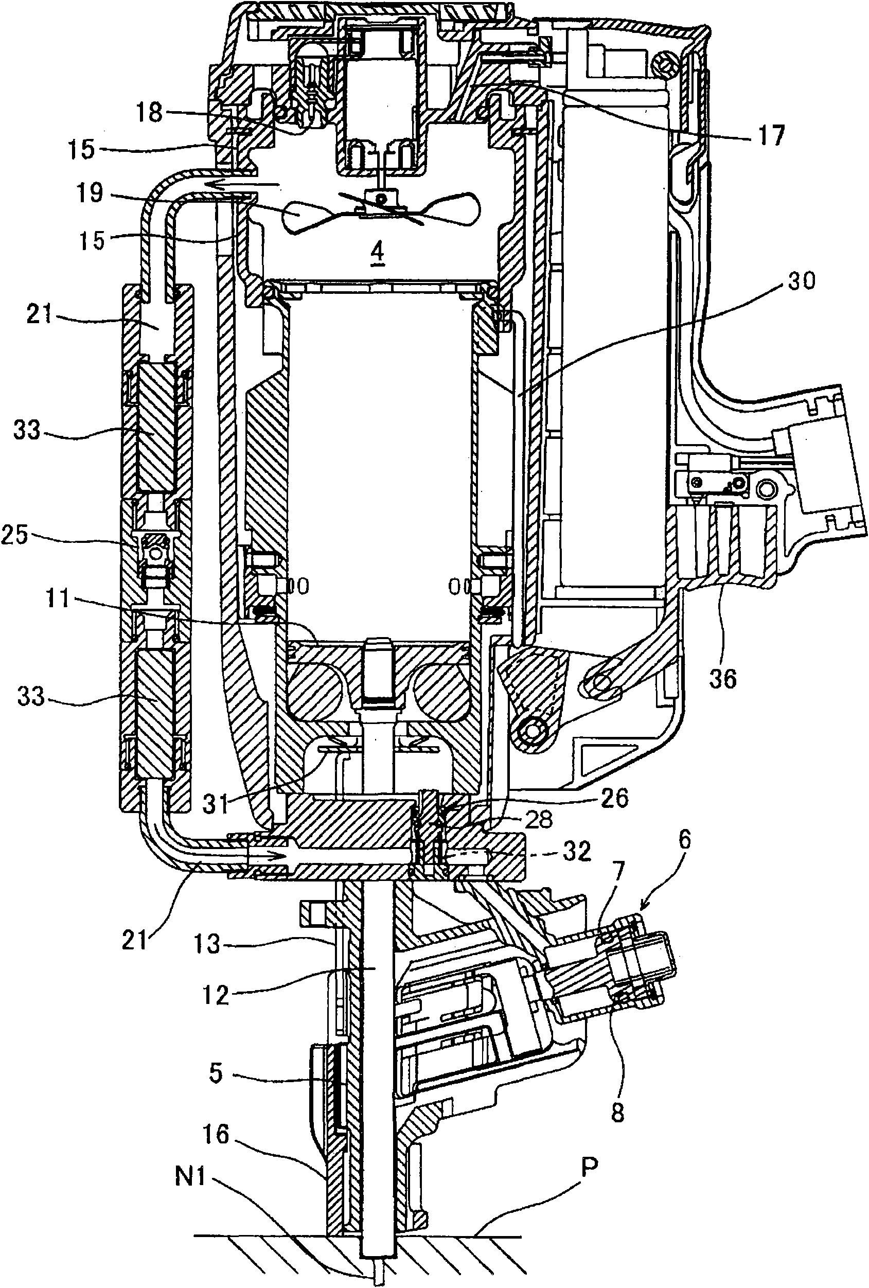
[0014] figure 1 Among them, reference numeral 1 represents the body of the gas combustion type nail driving device. The body 1 is provided in a continuous manner with a handle (not shown) and a nail magazine 2, but also with a hammering piston / cylinder mechanism 3, a combustion chamber 4, a nose portion 5 and a feed piston / cylinder for feeding the nails Institution 6.

[0015] The hammer piston / cylinder mechanism 3 includes a hammer piston 11 in a hammer cylinder 10 in a slidable manner, and is integrally connected with a driver 12 below the hammer piston 11 . It should be noted that the C-shaped snap ring 9 limits the upward movement of the hammer piston 11 .

[0016] The combustion chamber 4 is formed by the upper end face of the hammering piston 11; the upper wall 14 (cylinder head) formed in the upper casing 13; and the annular movable sleeve 15 between the aforementioned two elements. like figure 1 As shown, the device is constructed to pass as figure 2 Moving the m...


PUM


Abstract

Provided is a gas combustion type knock tool comprising a feed piston / cylinder mechanism (6) for reciprocating a feed piston (8), which is brought into and out of engagement with a connecting fastenerhoused in a magazine, in a fastener feeding direction to the side of a nose portion (5) and in the opposite retracting direction. The feed piston (8) is always spring-biased in the feeding direction,thereby to feed the combustion gas partially to a feed cylinder (7) through a gas passage (21) interposed between a combustion chamber (4) and the feed piston / cylinder mechanism (6), so that the feedpiston (8) is activated in the retracting direction against a spring (20). In the gas combustion type knock tool, a combustion gas cooling filter (33) is arranged in a midway portion of the gas passage (21).

Description

technical field [0001] The present invention relates to a gas combustion driving tool comprising: a combustion chamber in which a gas mixture obtained by agitating and mixing combustible gas and air burns violently; Combustion gas pressure drives out the fastener; and a feed piston / cylinder mechanism for feeding the fastener to the nose portion. The present invention provides an improved gas conduit through which combustion gases from a combustion chamber are supplied to a piston / cylinder mechanism for operating the mechanism. Background technique [0002] The gas combustion driving tool injects combustible gas into the combustion chamber sealed with the body to stir the gas mixture of combustible gas and air in the combustion chamber, and burns the stirred gas mixture in the combustion chamber, thereby generating high pressure in the combustion chamber combustion gas. In addition, this high-pressure combustion gas acts on a hammer piston contained in the hammer cylinder s...

Claims


Application Information

Patent Timeline
Patent Type & Authority Applications(China)
IPC IPC(8): B25C1/08B25C1/00
CPCB25C1/184B25C1/08
Inventor 田村纯一村山胜彦小西正和
Owner MAX CO LTD
Learn More