Lighting device and display device

一种照明装置、照明区域的技术,应用在照明装置、照明和加热设备、照明系统的光导等方向,能够解决显示器薄型化障碍等问题

Inactive Publication Date: 2010-03-31
SHARP KK
View PDF5 Cites 10 Cited by
  • Summary
  • Abstract
  • Description
  • Claims
  • Application Information

AI Technical Summary

Problems solved by technology

However, the thickness of conventional direct lighting devices is about 20 mm to 40 mm, which is an obstacle to further thinning of displays.

Method used


Image

  • Lighting device and display device
  • Lighting device and display device
  • Lighting device and display device

Examples


Embodiment approach 1

[0120] according to figure 1 (a), (b) to Figure 14 as well as Figure 32 , Figure 36 to Figure 38 One embodiment of the present invention will be described as follows.

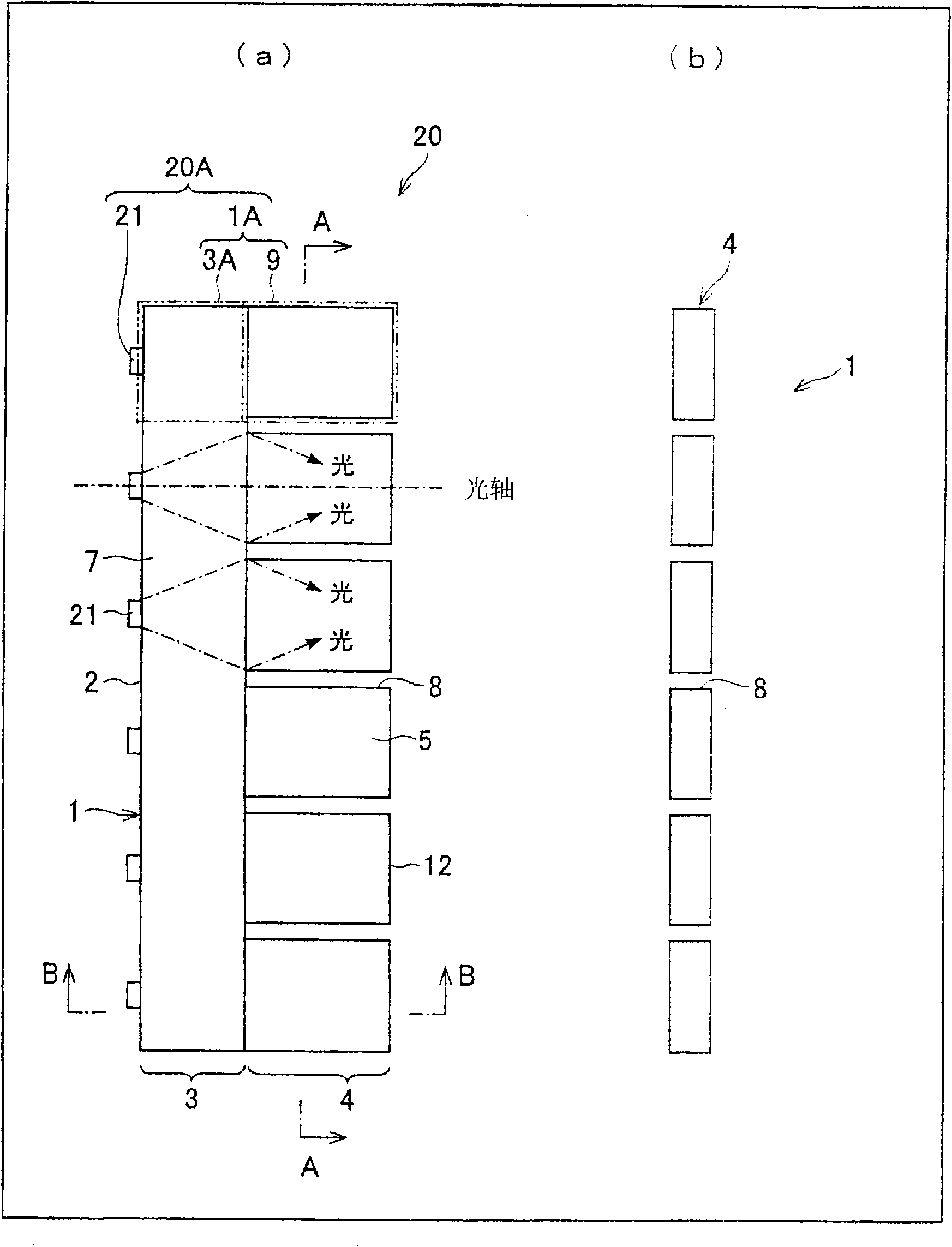
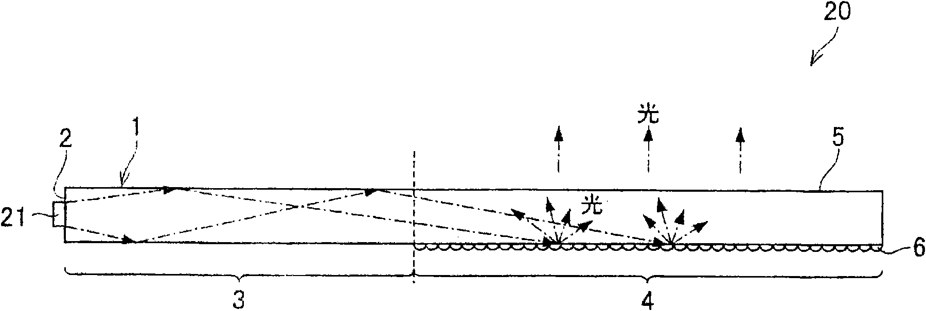
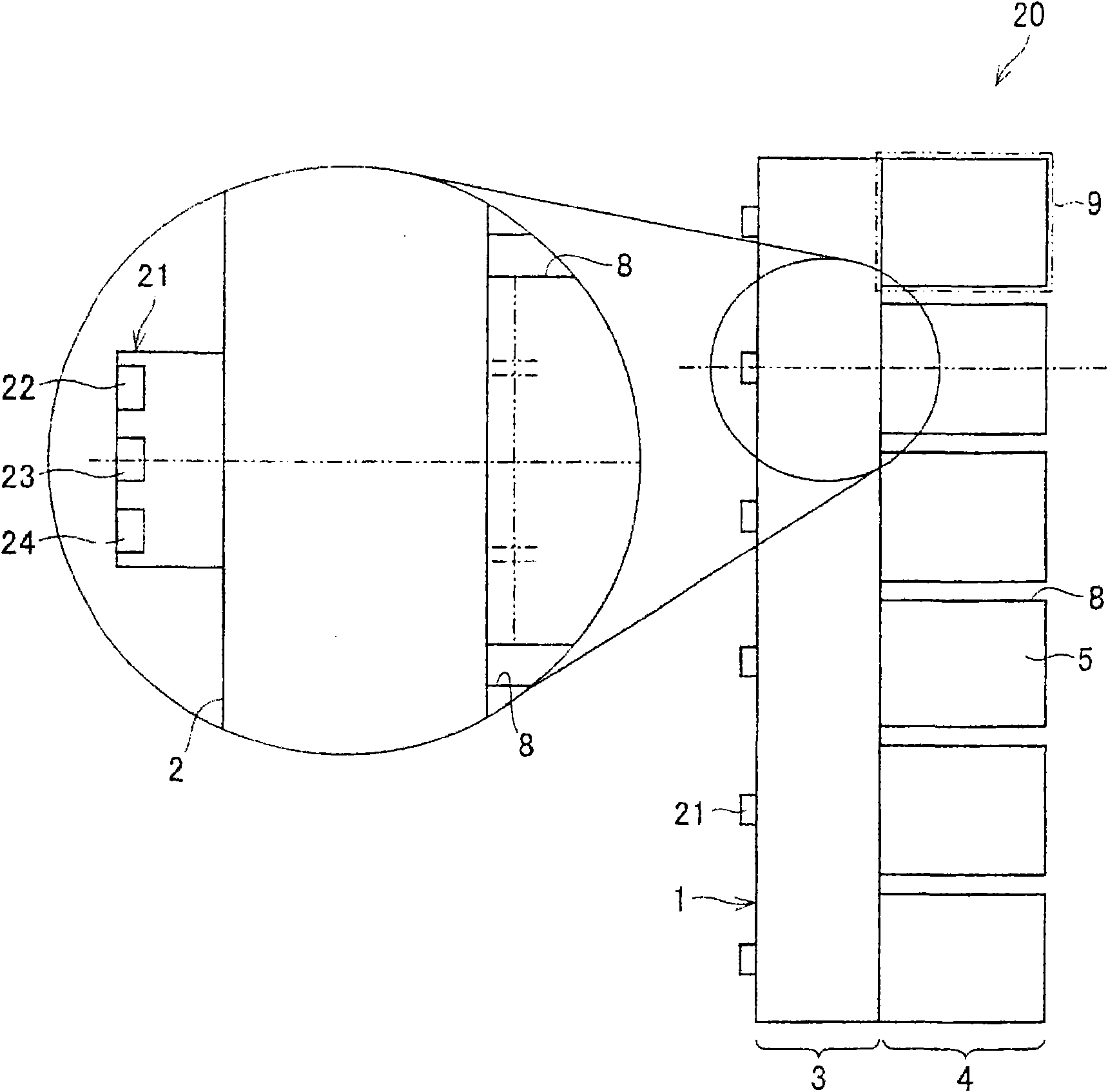
[0121] figure 1 (a) is a plan view showing a schematic configuration of a light source unit according to the present embodiment, figure 1 (b) is along figure 1 (a) A-A line sectional view of the light guide plate of the light source unit shown. figure 2 is along figure 1 (a) A cross-sectional view taken along the line B-B of the light source unit.

[0122] Such as figure 1 As shown in (a), the light source unit 20 of this embodiment includes a light guide plate 1 (light guide body) and a plurality of light sources 21 (point light sources) provided on one end surface of the light guide plate 1 .

[0123] The light source unit 20 is a side-light type light source unit (surface light source unit) provided with a light source 21 and emitting (surface emission) light incident from one end surface of the...

Embodiment approach 2

[0288] For this embodiment, mainly based on Figure 15 (a) and (b) are explained as follows. In addition, in this embodiment, the point which differs from Embodiment 1 mentioned above is demonstrated, and the structural element which has the same function as Embodiment 1 mentioned above is attached|subjected to the same code|symbol, and the description is abbreviate|omitted.

[0289] Figure 15 (a) is a plan view showing a schematic configuration of the light source unit 20 of this embodiment, Figure 15 (b) is along Figure 15 (a) is a sectional view taken along the line D-D of the light guide plate 1 of the light source unit 20 shown.

[0290] In the light source unit 20 of this embodiment, instead of figure 1 The slit portion 8 described in (a) and (b) is provided with a groove portion 13 (groove). That is, the light guide plate 1 of the present embodiment has a structure in which the illumination area 4 is divided into a plurality of light emitting sections 9 by repla...

Embodiment approach 3

[0303] For this embodiment, mainly based on Figure 16 (a), (b) and Figure 17 (a) and (b) are explained as follows. In this embodiment, differences from Embodiments 1 and 2 described above will be described, and constituent elements having the same functions as Embodiments 1 and 2 described above will be given the same reference numerals, and descriptions thereof will be omitted.

[0304] Figure 16 is a plan view showing a schematic configuration of the light source unit 20 of the present embodiment, Figure 16 (b) is Figure 16 (a) is a cross-sectional view taken along line E-E of the light guide plate 1 of the light source unit 20 shown. in addition, Figure 17 (a) is a plan view showing a schematic configuration of another light source unit 20 according to the present embodiment, Figure 17 (b) is Figure 17 (a) A cross-sectional view taken along the line F-F of the light guide plate 1 of the light source unit 20 shown.

[0305] The light source unit 20 of this em...


PUM

PropertyMeasurementUnit
refractive indexaaaaaaaaaa

Abstract

The invention relates to a lighting device and a display device. The lighting device includes light source units (20) each having a light guide plate and at least one light source. On the light guideplate, there are arranged next to each other a lighting region (4) for causing light entered from the light source to exit to the outside and a light guide region (3) for guiding to the lighting region (4) light entered from the light source. Light source units (20) adjacent to each other in the direction of the optical axis of the light source are arranged such that the lighting region (4) of onelight source unit (20) overlaps at least a part of the light guide region (3) of the other light source unit (20). Between the light guide plate (LG(k)) of the one light source unit (20) and the light source (BL(k+1)) of the other light source unit (20), there are arranged a diffusion reflection sheet (33), and a regular reflection sheet (32) or a light absorption sheet so as to be superposed oneach other. In the tandem type lighting device where the light guide plates are overlapped each other, irregular lighting is suppressed and luminance uniformity and color mixture properties are improved.

Description

technical field [0001] The present invention relates to a thin lighting device capable of area active driving and a display device using the lighting device. Background technique [0002] In recent years, liquid crystal display devices, which have rapidly spread instead of Braun tubes (CRTs), have been widely used in liquid crystal televisions, monitors, mobile phones, and the like, taking advantage of their features such as energy-saving, thin, and lightweight. As a method for further utilizing these features, improvement of an illumination device (so-called backlight) arranged behind a liquid crystal display device can be mentioned. [0003] Illumination devices are roughly divided into a side-light type (also referred to as an edge-light type) and a direct-light type. The edge-light type has a structure in which a light guide plate is provided behind the liquid crystal display panel, and a light source is provided on an end surface (horizontal end) of the light guide pla...

Claims


Application Information

Patent Timeline
Patent Type & Authority Applications(China)
IPC IPC(8): F21V8/00F21Y101/02G02F1/13357
CPCG02F1/133603G02B6/0068G02F1/133611G02B6/0043G02B6/0055G02B6/0028G02B6/008
Inventor 增田岳志味地悠作神德千幸
Owner SHARP KK
Why Eureka
Try Eureka