
A metal wire cutting and packing machine with lighting effect

A metal wire and laser cutting machine technology, applied in lighting applications, lighting device parts, lighting devices and other directions, can solve the problems of difficult to accurately control the cutting length, large storage area, difficult to compress and bundle, etc., to achieve automation The effect of production and packaging is neat and tidy, and the production efficiency is improved

Active Publication Date: 2019-05-21
广西振钢再生资源有限公司
View PDF7 Cites 0 Cited by
  • Summary
  • Abstract
  • Description
  • Claims
  • Application Information

AI Technical Summary

Problems solved by technology

[0002] At present, when using traditional mechanical cutting devices to cut fixed-length metal wires, its disadvantages are time-consuming and labor-intensive, and the cutting length is not easy to control accurately
In order to ensure the convenience and safety of transportation and storage, metal wires need to be fixed on the outside with metal belts (iron straps) or metal wires (iron wires, lead wires) after cutting; if the cut metal wires are not sorted and packaged, these metal belts Due to its thinness and various shapes, the wire is easy to puncture and cut the skin, it is difficult to compress and bundle, and it takes up a large area for storage, so it is very difficult to handle. processing, low degree of automation

Method used


Image

  • A metal wire cutting and packing machine with lighting effect
  • A metal wire cutting and packing machine with lighting effect

Examples


Embodiment 1

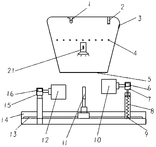
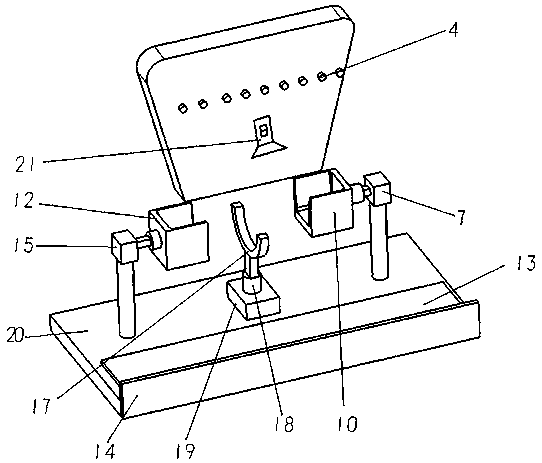
[0022] like figure 1As shown, a wire cutting baler with lighting effect includes a feeding device, a cutting device, a tally device, a baling device 11, and a conveying device; the feeding device is set as an inverted trapezoidal hollow box body, and the The feeding device includes a feeding port 3, a material limiting column 4 and a discharging port 5; the feeding port 3 is arranged above the side of the inverted trapezoidal hollow box body; the material limiting column 4 is arranged on the inverted trapezoidal hollow box body The middle position and runs through the box body; the discharge port 5 is set at the lower end of the inverted trapezoidal hollow box body; the cutting device includes a laser cutting machine and a photoelectric induction device 1, and the cutting hole 2 on the laser cutting machine is provided. on the inner side of the top of the inverted trapezoidal hollow box; the photoelectric sensing device 1 identifies the position of the wire and controls the la...

Embodiment 2

[0025] The second embodiment is basically the same as the first embodiment in structure and principle. The difference is that the material limiting column 4 is replaced with a folding spring stopper, which not only can realize the function of the material limiting column 4, but also has a simpler structure and principle and is convenient to operate.


PUM


Abstract

The invention discloses a metal wire cutting and packaging machine capable of providing illumination. The metal wire cutting and packaging machine comprises a feeding device, a cutting device, a cargoarrangement device, a packaging device and a conveying device. The cutting device comprises a laser cutting machine and a photoelectric induction device. The cargo arrangement device comprises a first connecting column, a spring column, a touch switch, a first bracket, a second bracket and a second connecting column. By means of the metal wire cutting and packaging machine, the traditional metalwire cutting and packaging mode can be improved; cutting of different lengths can be achieved through a photoelectric induction technology; in addition, the advanced laser technology is adopted as thecutting technology, production efficiency can be improved, automated control is promoted, and the whole process does not need involvement of manual work; cargo is packaged orderly and neatly; the weight is uniform, and errors are small; cutting and packaging work can be designed to be performed on multiple sets of cargo at the same time as needed, and efficient automated production can be achieved; and by means of an LED illuminating lamp, working conditions of the packaging device and the cargo arrangement device can be observed in real time, and the operation working condition of equipmentcan be known conveniently.

Description

technical field [0001] The invention belongs to the technical field of metal processing, and relates to a metal wire cutting baler with lighting function. Background technique [0002] At present, when using a traditional mechanical cutting device to cut a fixed-length metal wire, the disadvantage is that it is time-consuming and laborious, and the cutting length is not easy to accurately control. In order to ensure the convenience and safety of transportation and storage, after the metal wire is cut, it needs to be fixed with metal tape (iron packing tape) or metal wire (iron wire, lead wire) on the outside; if the cut metal wire is not sorted and packed, these metal tapes , Because of its lightness and thinness and various shapes, the wire is easy to puncture and cut the skin, and it is difficult to compress and bundle it. It occupies a large area for storage, and it is difficult to handle. processing, with a low degree of automation. SUMMARY OF THE INVENTION [0003] ...

Claims


Application Information

Patent Timeline
Patent Type & Authority Patents(China)
IPC IPC(8): B23K26/38B21F11/00B21C51/00B21F23/00B65B27/10B65B61/28B65B13/18F21V33/00F21W131/403F21Y115/10B23K101/32
CPCB21C51/00B21F11/00B21F23/00B23K26/38B23K2101/32B65B13/18B65B27/10B65B61/28F21V33/00F21W2131/403F21Y2115/10
Inventor 钟安祺
Owner 广西振钢再生资源有限公司
Learn More