Transmitter, transmitting method, receiver, and receiving method
A technology of a sending device and a receiving device, which is applied to the separation device of the transmission path, the transmission system, the equalizer, etc., can solve the problem of reducing the overall throughput, and achieve the effect of reducing the transmission efficiency and preventing the reduction of the overall throughput.
- Summary
- Abstract
- Description
- Claims
- Application Information
AI Technical Summary
Problems solved by technology
Method used
Image

Examples
Embodiment approach 1
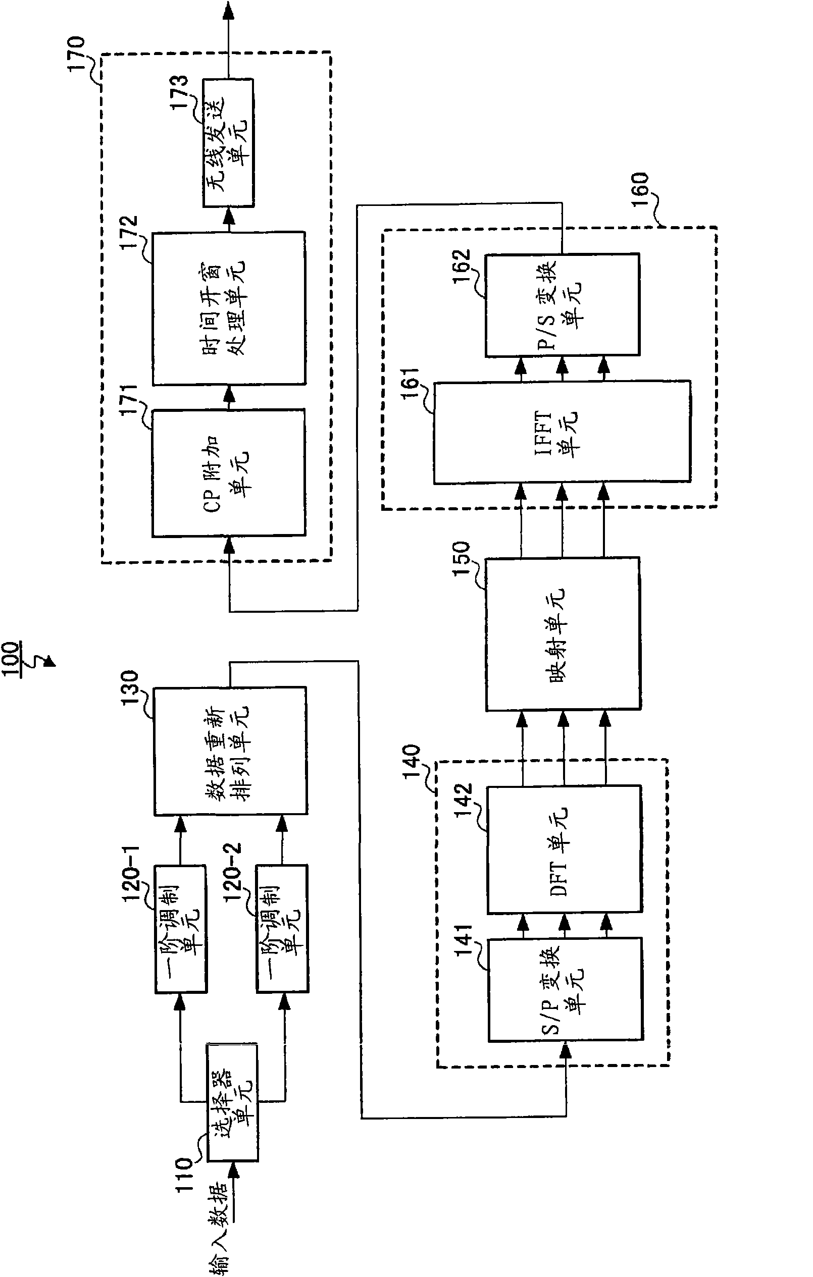
[0035] figure 2 The configuration of the main part of the transmission device according to the embodiment of the present invention is shown. figure 2 The structure of the transmission device 100 shown includes: a selector unit 110, first-order modulation units 120-1 and 120-2, a data rearrangement unit 130, a time-frequency conversion unit 140, a mapping unit 150, and a frequency-time conversion unit 160 and a wireless processing unit 170 .
[0036] The selector unit 110 distributes input data to the first order modulation units 120-1 and 120-2.
[0037] The first-order modulation units 120-1 and 120-2 support modulation modes of different modulation orders, respectively perform first-order modulation on the input data allocated by the selector unit 110, and output the obtained first-order modulation signals to the data rearrangement unit 130.
[0038] The data rearrangement unit 130 rearranges the primary modulation signals generated by the primary modulation units 120-1...
Embodiment approach 2
[0064] Figure 4 It is a block diagram showing the configuration of main parts of the transmission device 300 according to the embodiment of the present invention. In the description of this embodiment, for the figure 2 The same structural parts are given the same reference numerals, and descriptions thereof are omitted.
[0065] The difference from Embodiment 1 is that Figure 4 The selector unit 110 is deleted, and the data rearranging unit 310 is included in place of the data rearranging unit 130 in the transmitting device 300 of .
[0066] The data rearrangement unit 310 rearranges the first-order modulation signals generated by the first-order modulation units 120-1 and 120-2 according to the quality requirements of the input data input to the first-order modulation units 120-1 and 120-2, and generates 1SC - Time domain signal of FDMA symbol length.
[0067] Specifically, the data rearranging unit 310 preferentially allocates the first-order modulation signal corresp...
Embodiment approach 3
[0073] Figure 6 It is a block diagram showing the configuration of main parts of the transmission device 500 according to the embodiment of the present invention. In the description of this embodiment, for the figure 1 The same structural parts are given the same reference numerals, and descriptions thereof are omitted.
[0074] The difference from Embodiment 1 is that Figure 6 The selector unit 110 is deleted, and the data rearranging unit 510 is included in place of the data rearranging unit 130 in the transmitting apparatus 500 of .
[0075] The data rearrangement unit 510 rearranges these first-order modulation signals according to the wireless transmission characteristics corresponding to the first-order modulation signals generated by the first-order modulation units 120-1 and 120-2, and generates a time domain of 1SC-FDMA symbol length Signal.
[0076] Specifically, data rearranging section 510 preferentially allocates primary modulation signals with strong wirele...
PUM
 Abstract
Description
Claims
Application Information
 - R&D
- Intellectual Property
- Life Sciences
- Materials
- Tech Scout
- Unparalleled Data Quality
- Higher Quality Content
- 60% Fewer Hallucinations
Browse by: Latest US Patents, China's latest patents, Technical Efficacy Thesaurus, Application Domain, Technology Topic, Popular Technical Reports.
© 2025 PatSnap. All rights reserved.Legal|Privacy policy|Modern Slavery Act Transparency Statement|Sitemap|About US| Contact US: help@patsnap.com