
Bar code locating S/R machine

A stacker and bar code technology is applied in the field of electrical control devices for stacking and handling equipment in warehousing and logistics automated three-dimensional warehouses. and other problems, to achieve the effect of improving positioning accuracy and counting reliability, improving application occasions, and smooth starting and braking performance

Active Publication Date: 2011-11-09
上海精星仓储设备工程有限公司 +1
View PDF0 Cites 0 Cited by
  • Summary
  • Abstract
  • Description
  • Claims
  • Application Information

AI Technical Summary

Problems solved by technology

Among them, the address identification card positioning method is to perform address identification and positioning by reading the cargo location identification card. The positioning method is simple and economical, but its disadvantage is that this method belongs to discrete relative address identification, and the positioning accuracy is low. The impact is relatively large, and it is prone to omissions and miscalculations during high-speed operation, resulting in inaccurate address recognition and positioning
The laser ranging positioning uses a laser rangefinder for positioning, which belongs to continuous absolute addressing and high positioning accuracy, but its disadvantage is that it is only suitable for use in straight roads or roadways without obstacles, and cannot be used in turning or multi-curved roads. Stereo library
Therefore, no matter whether the address recognition chip is used for positioning or the laser ranging positioning has its own shortcomings and shortcomings

Method used


Image

  • Bar code locating S/R machine
  • Bar code locating S/R machine
  • Bar code locating S/R machine

Examples


Embodiment

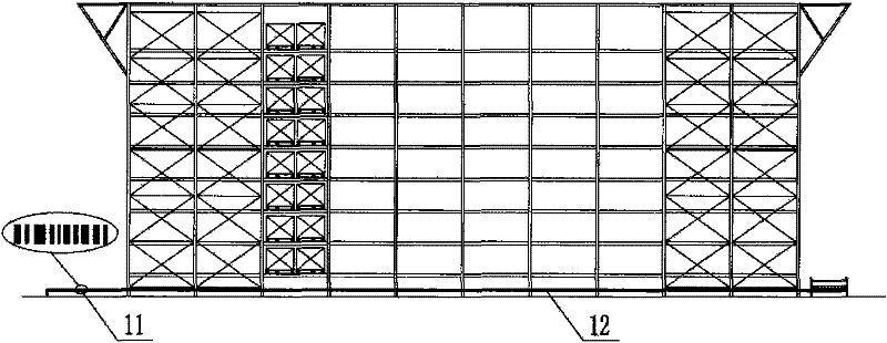
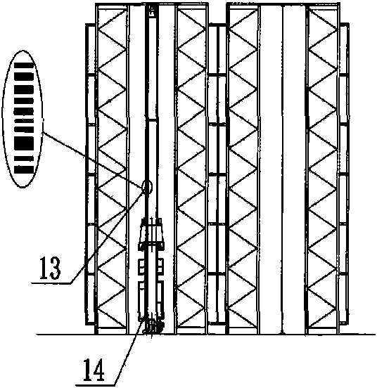
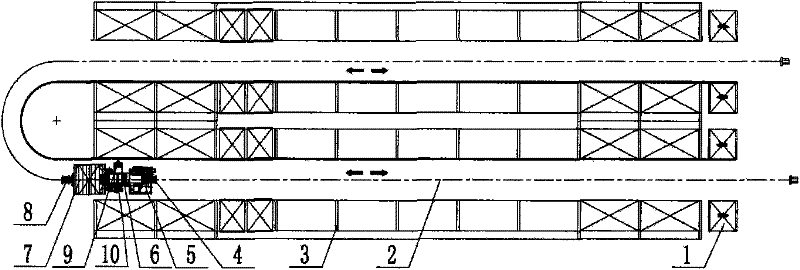
[0014] like Figure 1A , Figure 1B and Figure 1C As shown, it is a schematic diagram of the structure of the automated three-dimensional warehouse, including the inbound and outbound cargo platform 1, the sky and ground rail 2, the shelf 3 and the stacker 4. Rows of shelves 3 are arranged in the automated three-dimensional warehouse, each row of three-dimensional warehouse shelves 3 is provided with a cargo box, and ground rails 2 are arranged between every two rows of three-dimensional warehouse shelves 3, and the entrance and exit of the ground rails 2 There is an inbound and outbound cargo platform 1 at the end, and a stacker 4 that can travel back and forth on the ground rail 2 .

[0015] combine Figure 1A to Figure 1C and figure 2 To illustrate a barcode positioning stacker provided by the present invention, it includes a lower beam 8, an electric control cabinet 5 and a column 6 are arranged on the lower beam 8, a PLC is arranged in the electric control cabinet 5,...


PUM


Abstract

The invention relates to a bar code locating S / R machine which comprises a lower beam. An electric control cabinet and a mast are arranged on the lower beam, wherein a controller is arranged in the electric control cabinet, and a carriage which can move up and down is arranged on the mast. The bar code locating S / R machine is characterized in that a vertical bar code address recognizing device and a vertical address recognizing bar code strip are respectively arranged at the sides of the carriage and the mast; a horizontal bar code address recognizing device is arranged at the side of the lower beam; a horizontal address recognizing bar code strip is arranged at the side of a rack; and the input end of the controller is respectively connected with the output ends of the vertical bar code address recognizing device and the horizontal bar code address recognizing device. The bar code locating S / R machine of the invention has the advantages of improving location accuracy and calculation reliability, improving the flexibility of addressing and address recognizing to enable the S / R machine to have stable starting and braking performance, widening the application occasions of the S / R machine to enable the S / R machine to be widely used in straight lanes, bends or irregular and complex three-dimensional warehouses, has convenient use, simple structure, wide popularization and application value, and is economical and practical.

Description

technical field [0001] The invention relates to a barcode positioning stacker, which is used in an automated three-dimensional warehouse, enables the stacker to quickly and accurately measure distance and position, thereby improving the positioning accuracy and operating efficiency of the stacker, and belongs to the automatic three-dimensional warehouse stacker for warehousing and logistics. The technical field of electrical control devices for pallet handling equipment. Background technique [0002] At present, the stacker positioning generally adopts address recognition chip positioning and laser ranging positioning. Among them, the address identification card positioning method is to perform address identification and positioning by reading the cargo location identification card. The positioning method is simple and economical, but its disadvantage is that this method belongs to discrete relative address identification, and the positioning accuracy is low. The impact is ...

Claims


Application Information

Patent Timeline
Patent Type & Authority Patents(China)
IPC IPC(8): B66F9/07B66F9/075
Inventor 管树林杨光辉
Owner 上海精星仓储设备工程有限公司
Learn More