
Method used for detecting concentric circle of industrial part

A detection method and technology of concentric circles, applied in the direction of measuring devices, optical devices, image analysis, etc., can solve problems such as unusable, irregular part images, and increased difficulty in concentric circle detection

Inactive Publication Date: 2011-05-11
WUHAN UNIV
View PDF2 Cites 0 Cited by
  • Summary
  • Abstract
  • Description
  • Claims
  • Application Information

AI Technical Summary

Problems solved by technology

[0003] Industrial measurement has just started in China. At present, there are basically no mature detection methods for concentric circles. Coupled with the influence of image data noise in industrial detection and the high requirements for reliability and accuracy of industrial detection, the difficulty of concentric circle detection has increased.
The existing Hough transform method is commonly used to detect circles, but this method is only used in the case of regular single-line edges. In general, the quality of the image captured by the camera is not high, and the circle of the part image itself is sometimes irregular, which is not strictly meaningful. The circle on the circle, and the texture around the circle may be more complicated, so the points on the circle obtained after gradient and grayscale algorithms are not strictly a series of points on the edge of the circle, so the Hough transform cannot be used to obtain the position of the circle

Method used


Image

  • Method used for detecting concentric circle of industrial part
  • Method used for detecting concentric circle of industrial part
  • Method used for detecting concentric circle of industrial part

Examples


Embodiment Construction

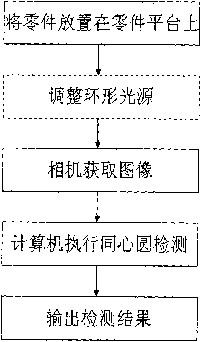
[0053] For the convenience of implementation and reference, the embodiment of the present invention provides a complete actual operation process of concentric circle detection starting from shooting. Among them, in addition to the existing technologies such as shooting methods, the present invention provides a new technical solution for detecting the original image obtained by shooting the concentric circles on the part, which can be automatically realized by computer means. The technical scheme of the present invention is described below in conjunction with accompanying drawing and embodiment:

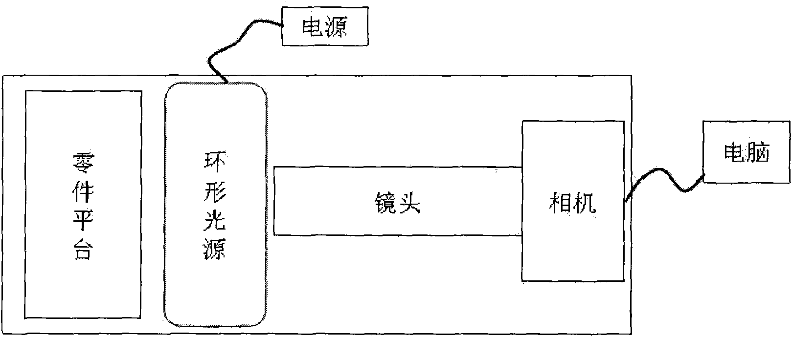
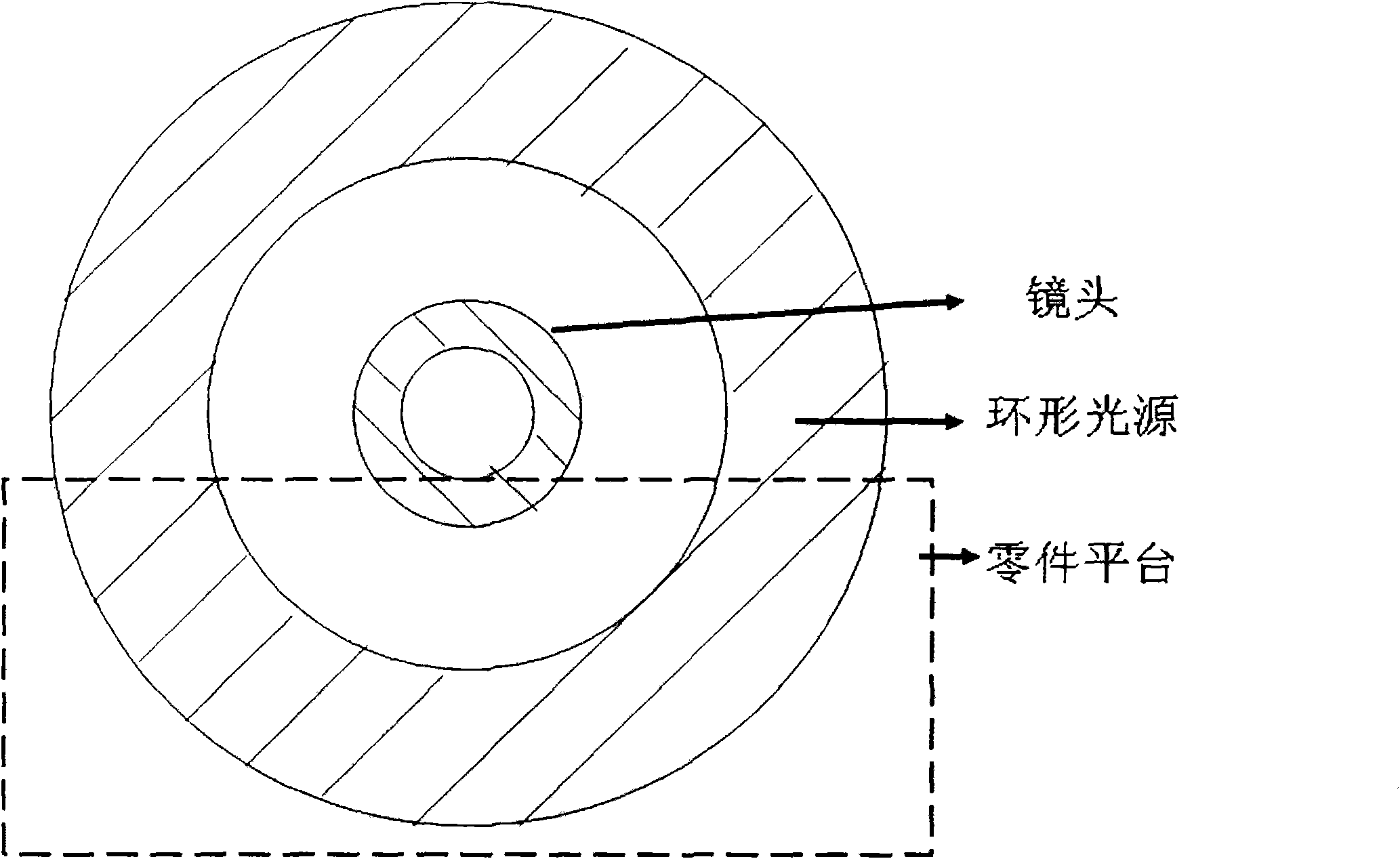
[0054] See attached figure 1 , the concentric circle detection hardware system of embodiment is made up of following parts:

[0055] (1) A camera with a lens. With a USB or 1394 data cable, the data can be transmitted to the computer in real time, the sampling frequency is 15 frames per second or above, and the resolution depends on the situation. It is recommended to use a resolut...


PUM


Abstract

The invention relates to a method used for detecting the concentric circle of an industrial part, which comprises the following steps: inputting the initial calibration parameter of the position of the concentric circle; detecting according to the initial calibration parameter; extracting a rectangular image from an original image and obtaining the gradient value of each pixel point in the rectangular image; searching the possible pixel points of an internal circle and an external circle according to the gray-scale value of the rectangular image, a gradient image and the initial calibration parameter; obtaining the fitting circle center coordinates and the fitting radius of the internal circle by the coordinate fitting internal circle of the possible pixel point of the internal circle; obtaining the fitting circle center coordinates and the fitting radius of the external circle by the coordinate fitting external circle of the possible pixel point of the external circle; and obtaining a distance between the fitting circle center coordinates of the internal circle and the fitting circle center coordinates of the external circle and judging whether a concentric condition is met or not according to the distance. The method can accurately identify and calculate the circle center and the radius of the concentric circle in an image shot by a camera and replace human eyes to judge whether the circle center and the radius meet requirements or not.

Description

technical field [0001] The invention relates to the field of industrial part detection, in particular to a concentric circle detection method realized by computer vision measurement. Background technique [0002] With the continuous development and progress of computers and computer vision, in the current detection of industrial parts, the demand for machine vision to replace human eyes to detect parts is becoming more and more urgent. The use of computer vision detection has many advantages, such as high detection accuracy, fast speed, and relatively good accuracy. In addition, the current hardware prices such as computers and cameras are not high, and the price of human resources continues to increase. Therefore, machine vision is used instead of human eyes. Detecting parts can greatly reduce costs, improve production efficiency, and improve the competitiveness and viability of enterprises. In the industrial field, there are many concentric circles, such as the connector ...

Claims


Application Information

Patent Timeline
Patent Type & Authority Patents(China)
IPC IPC(8): G01B11/27G06T7/00
Inventor 郑顺义王晓南左志奇
Owner WUHAN UNIV
Learn More