
Mold structure

A mold and material support technology is applied in the field of automatic uncoiling and blanking mold waste material support mechanism, which can solve the problems of high requirements, surface scratches, and the inability of cover molds to meet the use requirements.

Inactive Publication Date: 2010-05-05
CHERY AUTOMOBILE CO LTD
View PDF0 Cites 4 Cited by
  • Summary
  • Abstract
  • Description
  • Claims
  • Application Information

AI Technical Summary

Problems solved by technology

[0002] Auto body panel molds are the molds with the highest requirements and the most difficult processing in automobile body manufacturing, especially the side drawing dies have high requirements on the dimensional accuracy of the blanking pieces, and the quality problems of the blanking pieces may directly cause the failure of the panel molds. Meet the use requirements
Originally, it is not suitable to remove waste from the simple supporting rod mechanism. Most mold manufacturers are unwilling to use it. Some molds even omit this structure. The waste area naturally sags due to gravity, resulting in unstable product dimensions, surface scratches and other quality problems.
That is, there are the following technical problems in the prior art: the existing mold does not have a special support mechanism for the sheet metal

Method used


Image

  • Mold structure
  • Mold structure
  • Mold structure

Examples


Embodiment Construction

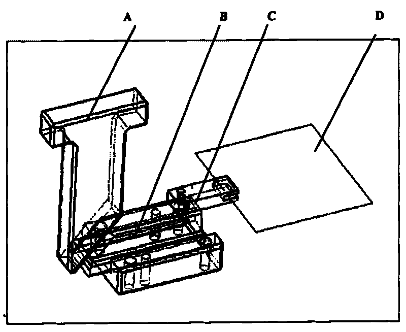
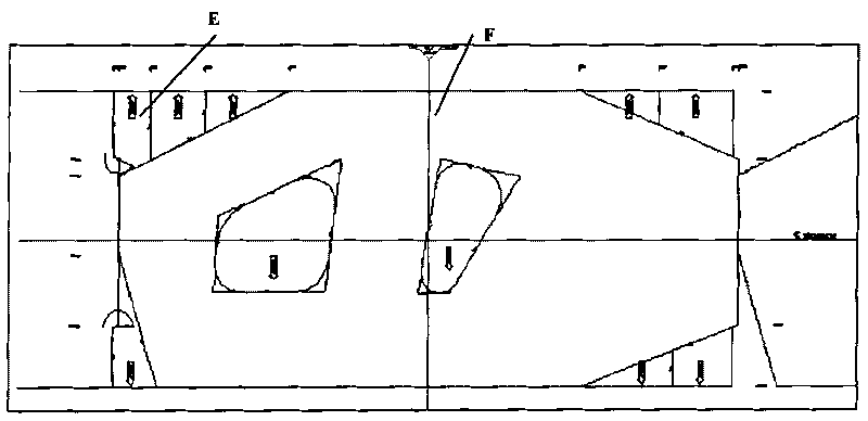
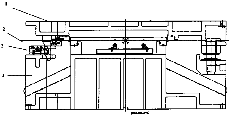
[0022] Referring to the accompanying drawings, through the description of the examples, the specific implementation of the mechanism of the present invention, such as the shape, structure, mutual position and connection relationship between the various parts, the function and working principle of each part, and the manufacturing process And operation and use methods, etc., for further detailed description, to help those skilled in the art have a more complete, accurate and in-depth understanding of the inventive concept and technical solutions of the utility model mechanism.

[0023] Such as figure 1 The mechanism technology of the present invention expressed, the mechanism of the present invention is a new type of mechanism for machining, short manufacturing time, improving product dimensional accuracy, solving product surface deformation and scratches, and allowing waste to slide freely. It is used for automatic uncoiling and blanking. use of structures. In order to solve t...


PUM


Abstract

The invention relates to a mold structure comprising a mold body. The mold body is provided with a sheet supporting mechanism used for supporting a sheet when the mold is used; the sheet supporting mechanism comprises a sheet supporting plate, a horizontal tapered wedge and a driven block; the sheet supporting plate is provided with a groove on one side and is used for supporting the sheet; one side of the horizontal tapered wedge is connected with the sheet supporting plate; the bottom inclined surface of the driven block is connected with the inclined surface on the other side of the horizontal tapered wedge and can be driven to move; the mold body comprises an upper mold and a lower mold; the sheet supporting mechanism is arranged between the upper mold and the lower mold; the driven block is arranged on the upper mold; and the horizontal tapered wedge is arranged on the lower mold.

Description

technical field [0001] The present invention relates to the technical field of pressure manufacturing process equipment, in particular to a mold structure, more specifically, it may be a cold stamping mold structure or an automatic uncoiling blanking mold waste material holding mechanism. Background technique [0002] Auto body panel molds are the molds with the highest requirements and the most difficult processing in automobile body manufacturing, especially the side drawing dies have high requirements on the dimensional accuracy of the blanking pieces, and the quality problems of the blanking pieces may directly cause the failure of the panel molds. Meet the requirements for use. Originally, the waste of the simple support rod mechanism should not be eliminated. Most mold manufacturers are unwilling to use it. Some molds even omit this structure. The waste area naturally sags due to gravity, resulting in unstable product dimensions, surface scratches and other quality pro...

Claims


Application Information

Patent Timeline
IPC IPC(8): B21D37/10B21D37/12B21D28/14
Inventor 郭道树
Owner CHERY AUTOMOBILE CO LTD
Learn More